Toyota Tacoma (2015-2018) Service Manual: Components
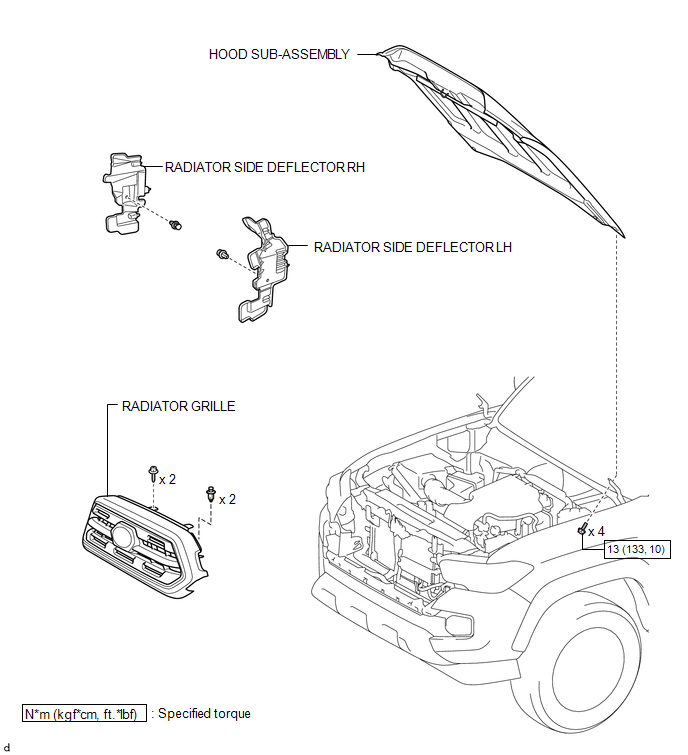
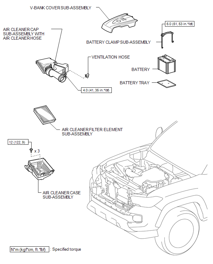
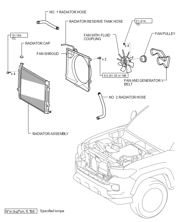
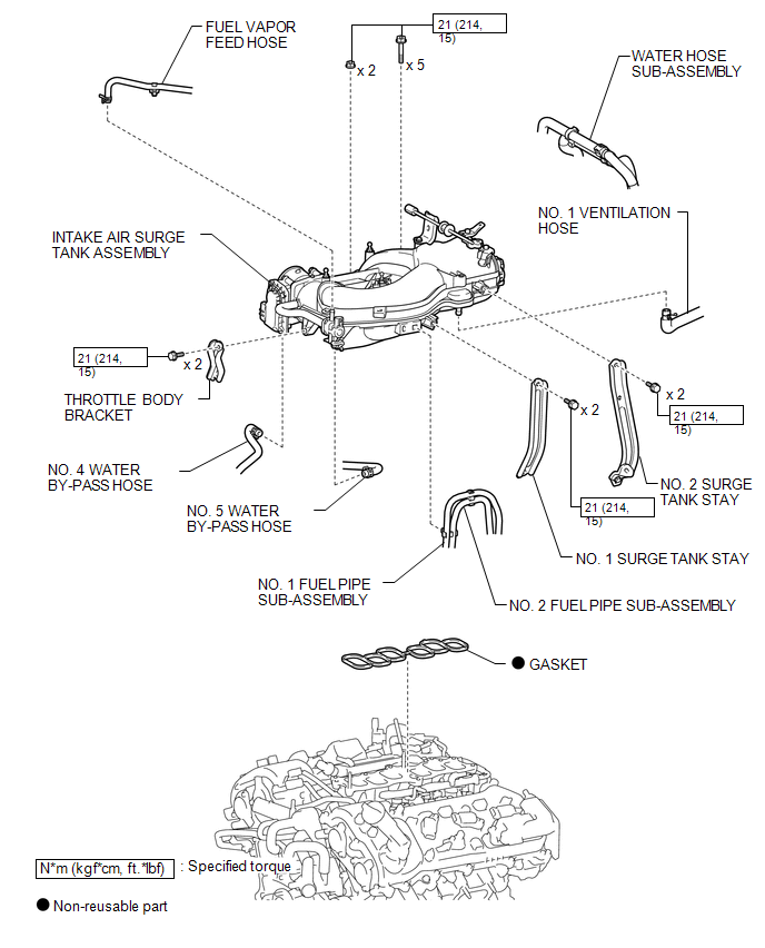
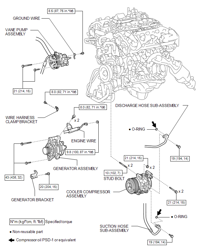
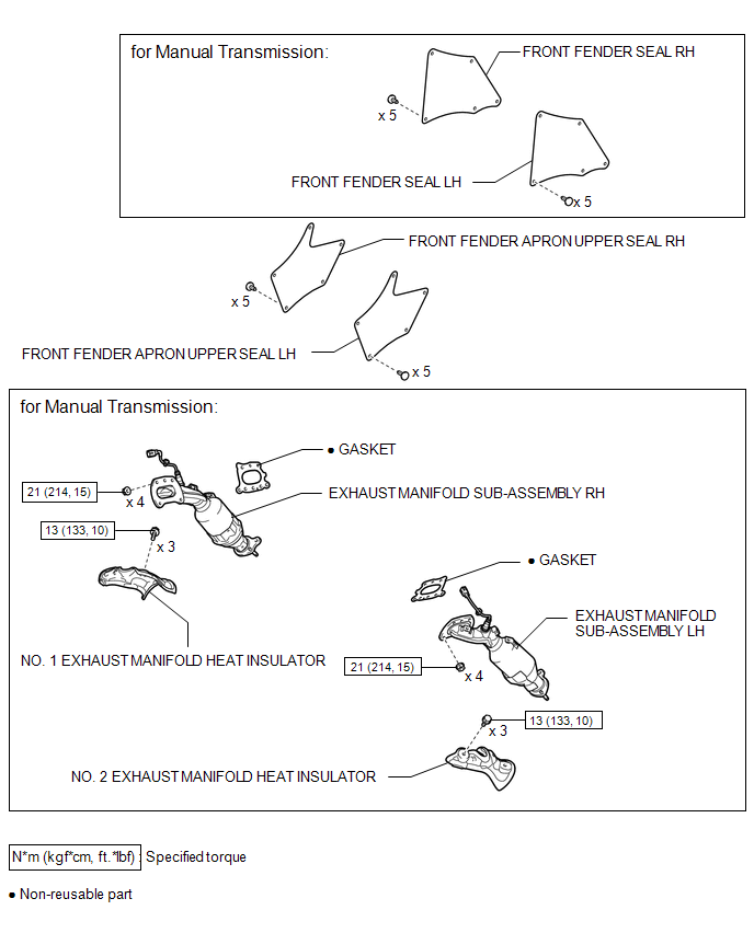
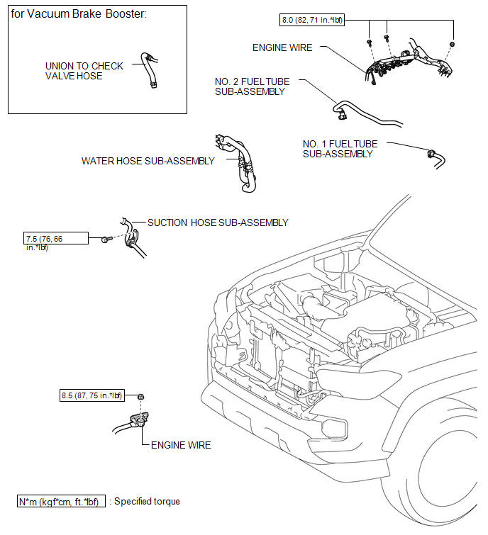
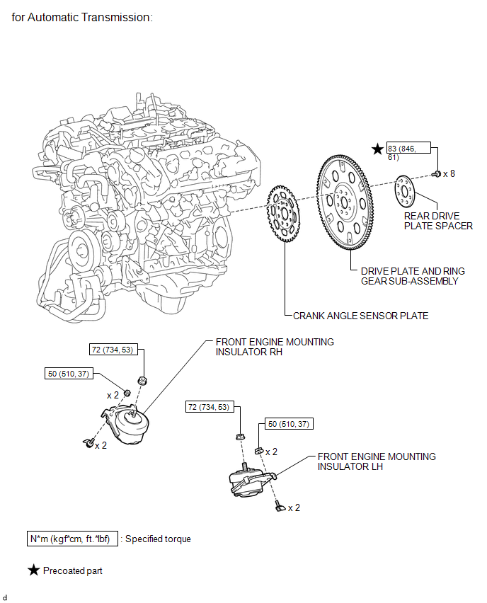
COMPONENTS
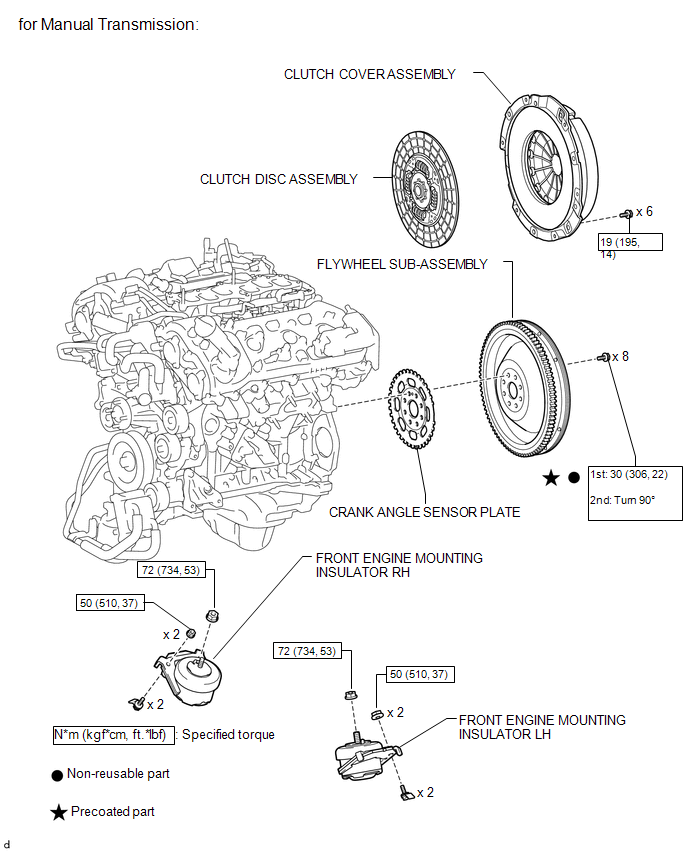
ILLUSTRATION
.png)
ILLUSTRATION
ILLUSTRATION
ILLUSTRATION
ILLUSTRATION
ILLUSTRATION
ILLUSTRATION
ILLUSTRATION
ILLUSTRATION
ILLUSTRATION
 Engine Assembly
...
 Installation
INSTALLATION
CAUTION / NOTICE / HINT
HINT:
Perform "Inspection After Repairs" after replacing the engine assembly, cylinder
head sub-assembly, camshaft, No. 2 camshaft, No. 3 camshaft s ...
Other materials:
Replacement
REPLACEMENT
PROCEDURE
1. REPLACE INTAKE VALVE GUIDE BUSH
(a) Heat the cylinder head to 80 to 100°C (176 to 212°F).
(b) Place the cylinder head on wooden blocks.
(c) Using SST and a hammer, tap out the intake valve guide bushes.
SST: 09201-10000
09201-01050
SST: 09950-70010 ...
Removal
REMOVAL
PROCEDURE
1. REMOVE SHIFT LEVER KNOB SUB-ASSEMBLY (for Automatic Transmission)
(a) Using a molding remover A, disengage the 2 claws to separate the
shifting hole cover sub-assembly.
(b) Rotate the shift lever knob sub-as ...
Engine Coolant Temperature Receiver Gauge Malfunction
DESCRIPTION
In this circuit, the meter CPU receives engine coolant temperature signals from
the ECM using the CAN communication system (CAN V1 Bus). The meter CPU displays
engine coolant temperature that is calculated based on the data received from the
ECM.
WIRING DIAGRAM
CAUTION / NOTIC ...
