Toyota Tacoma (2015-2018) Service Manual: Components
COMPONENTS
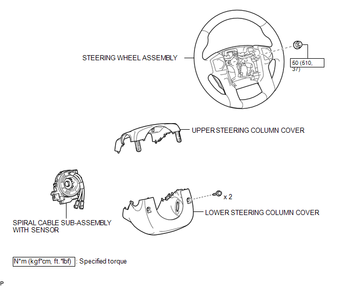
ILLUSTRATION

 Installation
INSTALLATION
PROCEDURE
1. INSTALL SPIRAL CABLE SUB-ASSEMBLY WITH SENSOR
(a) Check that the ignition switch is off.
(b) Check that the battery n ...
Other materials:
Air Mix Damper Position Sensor Circuit (Passenger Side) (B1431/31)
DESCRIPTION
This sensor detects the position of the air mix damper (for front passenger side)
and sends the appropriate signals to the air conditioning amplifier assembly. The
position sensor is built into the No. 2 air conditioning radiator damper servo sub-assembly
(for front passenger side ...
Portable Player cannot be Connected Manually/Automatically
CAUTION / NOTICE / HINT
HINT:
Some versions of "Bluetooth" compatible audio players may not function, or the
function may be limited using the radio and display receiver assembly, even if the
portable audio player itself can play files (See page
).
PROCEDURE
1.
...
Security Indicator Light Does not Blink
DESCRIPTION
The certification ECU (smart key ECU assembly) blinks the security indicator
light when the immobiliser is set (engine switch off, or driver door is
opened and closed with engine switch on (IG)).
The certification ECU (smart key ECU assembly) receive the security
...
