Toyota Tacoma (2015-2018) Service Manual: Inspection
INSPECTION
PROCEDURE
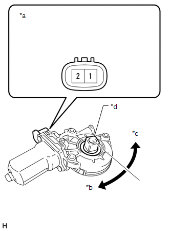
1. INSPECT POWER WINDOW REGULATOR MOTOR ASSEMBLY (for Power Slide Type)
|
*a |
Component without harness connected (Power Window Regulator Motor Assembly) |
|
*b |
Clockwise |
|
*c |
Counterclockwise |
|
*d |
Motor Gear |
(a) Check the operation of the power window regulator motor assembly.
(1) Apply battery voltage to the power window regulator motor assembly.
(2) Check that the motor gear rotates smoothly as follows.
OK:
|
Measurement Condition |
Specified Condition |
|---|---|
|
Battery positive (+) → 2 Battery negative (-) → 1 |
Motor gear rotates clockwise |
|
Battery positive (+) → 1 Battery negative (-) → 2 |
Motor gear rotates counterclockwise |
If the result is not as specified, replace the power window regulator motor assembly.
2. INSPECT NO. 1 POWER WINDOW RELAY
(a) Check the resistance.
|
(1) Measure the resistance according to the value(s) in the table below. Standard resistance:
If the result is not as specified, replace the No. 1 power window relay. |
|
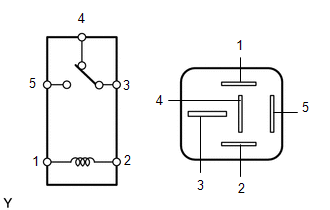
3. INSPECT NO. 2 POWER WINDOW RELAY
(a) Check the resistance.
|
(1) Measure the resistance according to the value(s) in the table below. Standard resistance:
If the result is not as specified, replace the No. 2 power window relay. |
|
 Components
COMPONENTS
ILLUSTRATION
*A
for Double Cab
*B
w/o Woofer
*C
w/ Woofer
-
-
*1
...
 Removal
REMOVAL
PROCEDURE
1. REMOVE REAR SEAT ASSEMBLY LH (for Double Cab)
Click here
2. REMOVE REAR SEAT ASSEMBLY RH (for Double Cab)
Click here
3. REMOVE REAR DOOR SCUFF PLATE LH (for Double Cab)
...
Other materials:
Short in GPS Antenna (B15C0,B15C1)
DESCRIPTION
These DTCs are stored when a malfunction occurs in the navigation antenna assembly.
DTC No.
DTC Detection Condition
Trouble Area
B15C0
Navigation antenna error
Navigation antenna assembly
Radio and ...
Steering Pad Switch Circuit
DESCRIPTION
This circuit sends an operation signal from the steering pad switch assembly
to the navigation receiver assembly.
If there is an open in the circuit, the audio system cannot be operated using
the steering pad switch assembly.
If there is a short in the circuit, the same condition ...
Removal
REMOVAL
PROCEDURE
1. REMOVE FUEL PUMP ASSEMBLY (for High Pressure)
(See page )
2. REMOVE NO. 2 FUEL PIPE SUB-ASSEMBLY
(a) Loosen the 2 union nuts and remove the No. 2 fuel pipe sub-assembly from
the fuel delivery pipe RH and fuel delivery pipe sub-assembly LH.
Text in Illustration
...
