Toyota Tacoma (2015-2018) Service Manual: Components
COMPONENTS
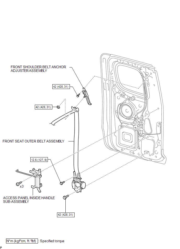
ILLUSTRATION

ILLUSTRATION

 Installation
INSTALLATION
CAUTION / NOTICE / HINT
HINT:
Use the same procedure for both the RH and LH sides.
The procedure described below is for the LH side.
PROCEDURE
1. INSTALL FRONT SHOU ...
Other materials:
Event data recorder
This vehicle is equipped with an event data recorder (EDR). The main purpose
of an EDR is to record, in certain crash or near crash-like situations, such as
an air bag deployment or hitting a road obstacle, data that will assist in understanding
how a vehicle’s systems performed. The EDR is ...
Cellular Phone cannot Send/Receive
PROCEDURE
1.
CHECK "Bluetooth" SETTINGS
(a) Check if the cellular phone is registered as a connected device and the "Bluetooth"
settings are correct.
OK:
The cellular phone is registered as a connected device and "Bluetooth" settin ...
Rear Right Sensor Malfunction (C1AE9)
DESCRIPTION
The No. 1 ultrasonic sensor (rear corner sensor RH) is installed on the rear
bumper. The ECU detects obstacles based on signals received from the No. 1 ultrasonic
sensor (rear corner sensor RH). If the No. 1 ultrasonic sensor (rear corner sensor
RH) has an open circuit or other ma ...
