Toyota Tacoma (2015-2018) Service Manual: Components
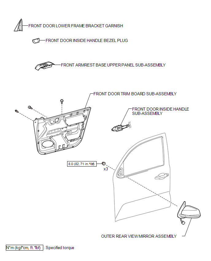
COMPONENTS
ILLUSTRATION
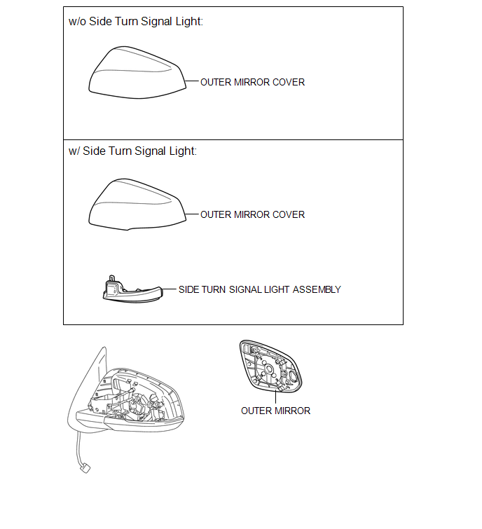
ILLUSTRATION

 Removal
REMOVAL
CAUTION / NOTICE / HINT
HINT:
Use the same procedures for both the LH and RH sides.
The procedure described below is for the LH side.
PROCEDURE
1. REMOVE FRONT DOOR LOWE ...
Other materials:
Check For Intermittent Problems
CHECK FOR INTERMITTENT PROBLEMS
1. DESCRIPTION
HINT:
A momentary interruption (open circuit) in the connectors and/or wire harness
between the sensors and ECUs can be detected through the ECU data monitor function
of the Techstream.
(a) Turn the ignition switch off.
(b) Connect the Techstre ...
Data List / Active Test
DATA LIST / ACTIVE TEST
1. DATA LIST
HINT:
Using the Techstream to read the Data List allows the values or states of switches,
sensors, actuators and other items to be read without removing any parts. This non-intrusive
inspection can be very useful because intermittent conditions or signals ...
Front Airbag Sensor LH Circuit Malfunction (B1615/14)
DESCRIPTION
The front airbag sensor LH consists of parts such as the diagnostic circuit and
the frontal detection sensor.
When the airbag sensor assembly receives signals from the frontal deceleration
sensor, it determines whether or not the SRS should be activated.
DTC B1615/14 is set when a ...
