Toyota Tacoma (2015-2018) Service Manual: Components
COMPONENTS
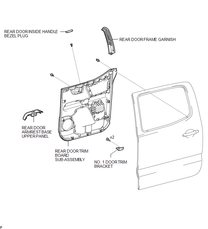
ILLUSTRATION
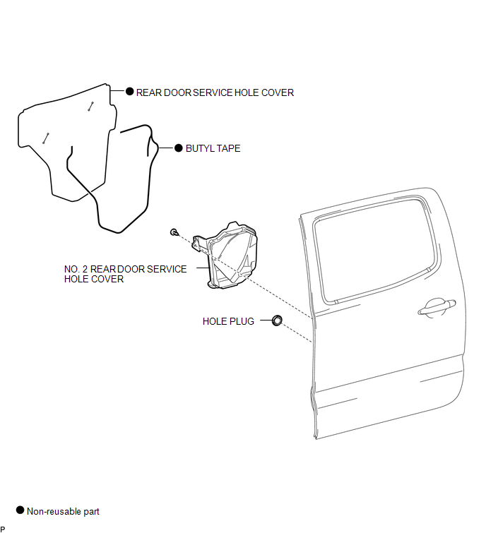
ILLUSTRATION
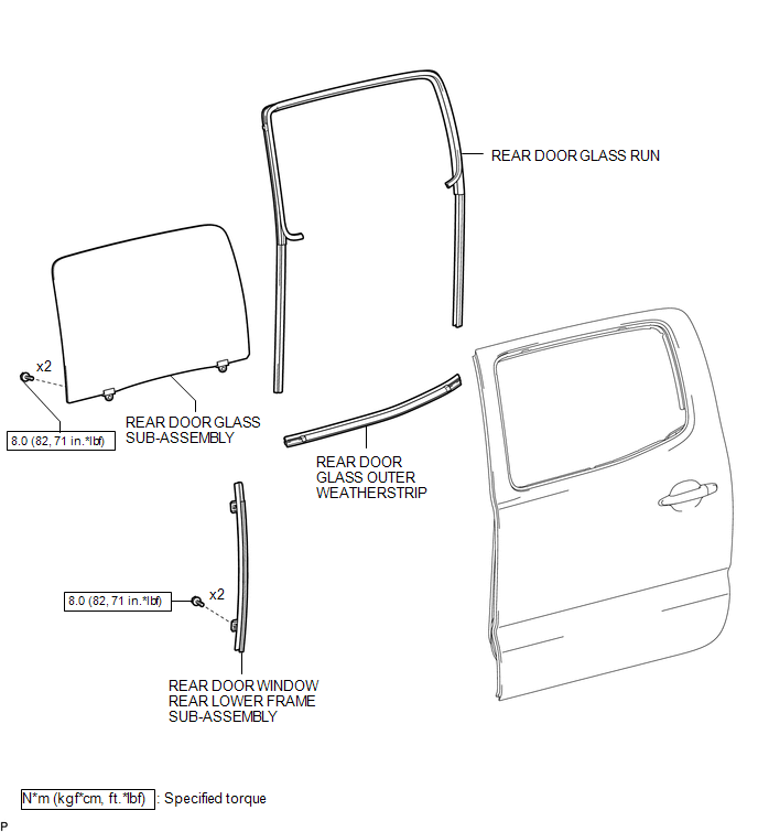
ILLUSTRATION

 Installation
INSTALLATION
CAUTION / NOTICE / HINT
HINT:
Use the same procedure for the RH side and LH side.
The following procedure is for the LH side.
PROCEDURE
1. INSTALL REAR DOOR GLASS O ...
Other materials:
Data List / Active Test
DATA LIST / ACTIVE TEST
1. DATA LIST
NOTICE:
In the table below, the values listed under "Normal Condition" are reference
values. Do not depend solely on these reference values when deciding whether a part
is faulty or not.
HINT:
Using the Techstream to read the Data List allows t ...
Brake Switch "A" Circuit Open (P057113)
DESCRIPTION
When the brakes are applied by the dynamic radar cruise control system, the skid
control ECU (master cylinder solenoid)*1 or skid control ECU (brake actuator assembly)*2
operates the stop light switch assembly (stop light relay) to illuminate the stop
lights.
If the ECM receives ...
Installation
INSTALLATION
PROCEDURE
1. INSTALL REAR AXLE SHAFT OIL SEAL
(a) Using SST and a hammer, install a new oil seal.
SST: 09950-60020
09951-00770
SST: 09950-70010
09951-07150
2. INSTALL REAR AXLE SHAFT WITH BACKING PLATE
(a) Install a new O-ring.
(b) Install the rear axle shaft with backing ...
