Toyota Tacoma (2015-2018) Service Manual: Components
COMPONENTS
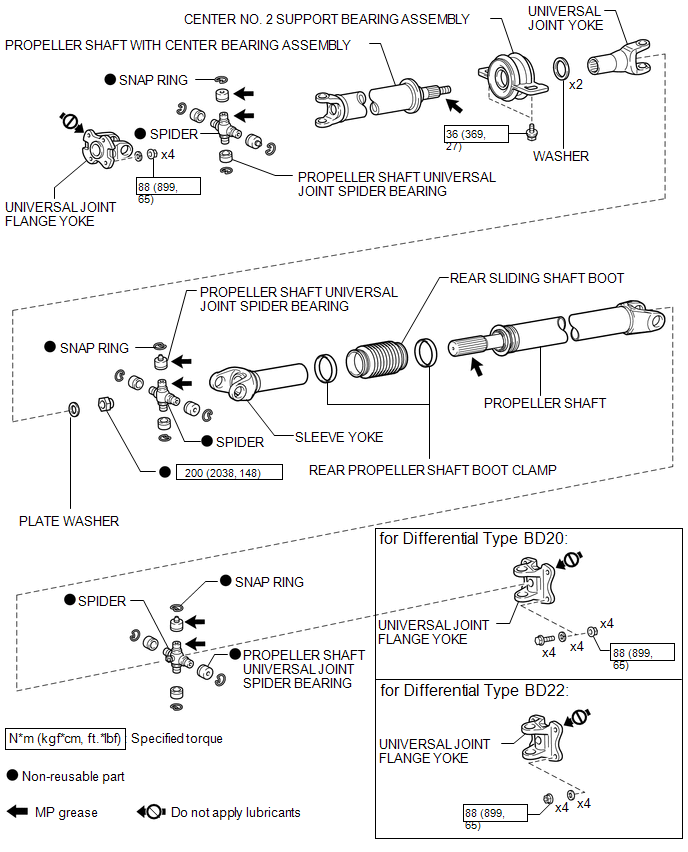
ILLUSTRATION

 Removal
REMOVAL
PROCEDURE
1. REMOVE PROPELLER SHAFT WITH CENTER BEARING ASSEMBLY
(a) Place matchmarks on the propeller shaft flange yoke and differential
flange.
Text in Illustration
...
Other materials:
Diagnostic Trouble Code Chart
DIAGNOSTIC TROUBLE CODE CHART
Rear View Monitor System
DTC Code
Detection Item
See page
C1622
Open or Short Circuit in Back Camera Signal
...
Downhill Assist Control system
The downhill assist control system helps to prevent excessive speed on steep
downhill descents.
■ System operation
The system will operate when the vehicle is traveling under 15 mph (25 km/h)
and the front-wheel drive control switch is in the L4 position.
Press the DAC switch. The ind ...
Cruise Control Input Processor (P160700)
DESCRIPTION
The ECM continuously monitors its main and sub CPUs. This self-check ensures
that the ECM is functioning properly. If outputs from the CPUs are different and
deviate from the standard, the ECM will illuminate the MIL and store the DTC.
DTC No.
Detection Item
...
