Toyota Tacoma (2015-2018) Service Manual: Communication Malfunction between ECUs Connected by LIN (B2785)
DESCRIPTION
The certification ECU (smart key ECU assembly) monitors communication between all the ECUs connected to the certification bus lines. When the certification ECU (smart key ECU assembly) detects errors in communication with all the ECUs connected to the certification bus lines at a set interval and 3 times in a row, DTC B2785 will be stored.
|
DTC No. |
DTC Detection Condition |
Trouble Area |
|---|---|---|
|
B2785 |
|
|
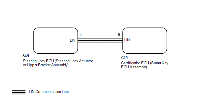
WIRING DIAGRAM
CAUTION / NOTICE / HINT
NOTICE:
- If the certification ECU (smart key ECU assembly) is replaced, register
the keys (See page
.gif) ).
). - If the steering lock ECU (steering lock actuator or upper bracket assembly)
is replaced, register the ECU code (See page
).
- When using the Techstream with the vehicle ignition switch off, connect the Techstream to the vehicle and turn a courtesy light switch on and off at intervals of 1.5 seconds or less until communication between the Techstream and the vehicle begins. Then select the vehicle type under manual mode and enter the following menus: Body Electrical / Smart Access. While using the Techstream, periodically turn a courtesy light switch on and off at intervals of 1.5 seconds or less to maintain communication between the Techstream and the vehicle.
PROCEDURE
|
1. |
CHECK HARNESS AND CONNECTOR (CERTIFICATION ECU (SMART KEY ECU ASSEMBLY) - STEERING LOCK ECU (STEERING LOCK ACTUATOR OR UPPER BRACKET ASSEMBLY)) |
(a) Disconnect the C29 certification ECU (smart key ECU assembly) connector.
(b) Disconnect the S45 steering lock ECU (steering lock actuator or upper bracket assembly) connector.
(c) Measure the resistance according to the value(s) in the table below.
Standard Resistance:
|
Tester Connection |
Condition |
Specified Condition |
|---|---|---|
|
C29-6 (LIN) - S45-5 (LIN) |
Always |
Below 1 Ω |
|
C29-6 (LIN) or S45-5 (LIN) - Body ground |
Always |
10 kΩ or higher |
| NG | .gif) |
REPAIR OR REPLACE HARNESS OR CONNECTOR |
|
.gif)
|
2. |
CHECK DTC OUTPUT (STEERING LOCK ECU (STEERING LOCK ACTUATOR OR UPPER BRACKET ASSEMBLY)) |
(a) Reconnect the C29 certification ECU (smart key ECU assembly) connector.
(b) Clear the DTCs (See page ).
(c) Recheck for DTCs.
|
Result |
Proceed to |
|---|---|
|
DTC B2785 is output |
A |
|
DTC B2785 is not output |
B |
| A | |
REPLACE CERTIFICATION ECU (SMART KEY ECU ASSEMBLY) |
| B | |
REPLACE STEERING LOCK ECU (STEERING LOCK ACTUATOR OR UPPER BRACKET ASSEMBLY) |
 Dtc Check / Clear
DTC CHECK / CLEAR
1. CHECK DTC
(a) Connect the Techstream to the DLC3.
(b) Turn the ignition switch to ON.
(c) Turn the Techstream on.
(d) Enter the following menus: Body Electrical / Smart Acces ...
 No Response from Steering Lock ECU (B2786)
DESCRIPTION
This DTC is stored when LIN communication between the certification ECU (smart
key ECU assembly) and steering lock ECU (steering lock actuator or upper bracket
assembly) stops for 10 ...
Other materials:
Pressure Control Solenoid "A" Performance (Shift Solenoid Valve SL1) (P0746)
SYSTEM DESCRIPTION
The ECM uses the vehicle speed signal and signals from the transmission revolution
sensors (NT, SP2) to detect the actual gear (1st, 2nd, 3rd, 4th, 5th or 6th gear).
The ECM compares the actual gear with the shift schedule in the ECM memory to
detect mechanical problems of t ...
Sun visors
Type A
Forward position: Flip down.
Side position: Flip down, unhook,
and swing to the side.
Type B
Forward position: Flip down.
Side position: Flip down, unhook,
and swing to the side.
Side extender: Place in side position,
then slide backwards. ...
Rear Door(for Access Cab)
Adjustment
ADJUSTMENT
CAUTION / NOTICE / HINT
HINT:
Use the same procedures for both the LH and RH sides.
The procedure described below is for the LH side.
Centering bolts are used to mount the door hinge to the vehicle body
and door. The door cannot be adjusted with the ce ...
