Toyota Tacoma (2015-2018) Service Manual: Check Mode Procedure
CHECK MODE PROCEDURE
1. DESCRIPTION
(a) Check mode has a higher sensitivity to malfunctions and can detect malfunctions that normal mode cannot detect. Check mode can also detect all the malfunctions that normal mode can detect. In check mode, DTCs are detected with 1 trip detection logic.
2. CHECK MODE PROCEDURE
(a) Make sure that the following conditions are met:
(1) Battery positive voltage 11 V or higher.
(2) Throttle valve fully closed.
(3) Shift lever in P or N.
(4) Air conditioning off.
(b) Turn the ignition switch off.
(c) Connect the Techstream to the DLC3.
(d) Turn the ignition switch to ON.
(e) Turn the Techstream on.
(f) Enter the following menus: Powertrain / Transmission / Utility / Check Mode.
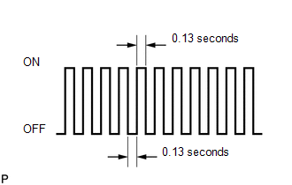
(g) Change the ECM to check mode. Make sure the MIL flashes as shown in the illustration.
NOTICE:
All DTCs and freeze frame data will be cleared if: 1) the Techstream is used to change the ECM from normal mode to check mode or vice versa; or 2) during check mode, the ignition switch is turned from ON to ACC or off.
Before entering check mode, make notes of the DTCs and freeze frame data.
(h) Start the engine. The MIL should turn off after the engine starts.
(i) Perform Monitor Drive Pattern for the ECT test (See page
.gif) ).
).
(Or, simulate the conditions of the malfunction described by the customer.)
(j) After simulating the malfunction conditions, use the Techstream to check the DTC and freeze frame data.
 Terminals Of Ecm
TERMINALS OF ECM
1. ECM
HINT:
The standard voltage between each pair of ECM terminals is shown in the table
below. In the table, first follow the information under "Condition". Look u ...
 Diagnosis System
DIAGNOSIS SYSTEM
1. DESCRIPTION
(a) When troubleshooting OBD II (On-Board Diagnostics) vehicles, an OBD II scan
tool (complying with SAE J1978) must be connected to the DLC3 (Data Link Connector
...
Other materials:
Microphone Amplifier
Components
COMPONENTS
ILLUSTRATION
*A
w/o Sliding Roof
*B
w/ Sliding Roof
*1
TELEPHONE MICROPHONE ASSEMBLY
-
-
Removal
REMOVAL
PROCEDURE
1. REMOVE ROOF HEADLINING ASSEMBLY (for Double ...
Precaution
PRECAUTION
1. CAUTION REGARDING INTERFERENCE WITH ELECTRONIC DEVICES
CAUTION:
People with implantable cardiac pacemakers, cardiac resynchronization
therapy-pacemakers or implantable cardioverter defibrillators should keep
away from the smart key system antennas. The radio waves ma ...
Problem Symptoms Table
PROBLEM SYMPTOMS TABLE
HINT:
Use the table below to help determine the cause of problem symptoms.
If multiple suspected areas are listed, the potential causes of the symptom
are listed in order of probability in the "Suspected Area" column of the
table. Check each sym ...
