Toyota Tacoma (2015-2018) Service Manual: Brake Switch "A" Circuit (P0571)
DESCRIPTION
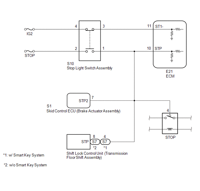
- When the brake pedal is depressed, the stop light switch assembly outputs a signal to the ECM. When the ECM receives the signal, it cancels control of vehicle speed by the dynamic radar cruise control system. The fail-safe function operates to enable normal operation even if there is a malfunction in the stop light signal circuit. The cancellation condition occurs when voltage is applied to terminal STP. When the brake pedal is depressed, voltage is applied to terminal STP of the ECM through the STOP fuse and the stop light switch assembly, and the ECM turns the dynamic radar cruise control system off.
- The ECM receives the brake demand signal from the millimeter wave radar sensor assembly and transmits it to the skid control ECU (brake actuator assembly). The skid control ECU (brake actuator assembly) receives a signal from the ECM and operates the skid control ECU (brake actuator assembly). The skid control ECU (brake actuator assembly) operates the brake actuator assembly and illuminates the stop lights.
|
DTC No. |
Detection Item |
DTC Detection Condition |
Trouble Area |
|---|---|---|---|
|
P0571 |
Brake Switch "A" Circuit |
Condition 1:
Condition 2:
|
Condition 1:
Condition 2:
|
WIRING DIAGRAM
CAUTION / NOTICE / HINT
NOTICE:
- Inspect the fuses for circuits related to this system before performing the following procedure.
- Before replacing the ECM, refer to Registration.
w/o Smart Key System: Click here
.gif)
w/ Smart Key System: Click here
PROCEDURE
|
1. |
CHECK FOR DTCs (VEHICLE STABILITY CONTROL SYSTEM) |
(a) Check for DTCs.
Click here
HINT:
When DTC P0571 (detection condition 2) is stored by the dynamic radar cruise control system, DTC C1380 is stored by the vehicle stability control system. Therefore, if DTC P0571 (detection condition 2) is stored, inspect the vehicle stability control system first.
|
Result |
Proceed to |
|---|---|
|
Vehicle stability control system DTCs are not output |
A |
|
Vehicle stability control system DTCs are output |
B |
| B | .gif) |
GO TO VEHICLE STABILITY CONTROL SYSTEM |
|
.gif)
|
2. |
CHECK FOR DTC (RADAR CRUISE1) |
(a) Clear the DTCs.
Click here
(b) Make sure that the DTC detection conditions are met.
HINT:
If the detection conditions are not met, the system cannot detect the malfunction.
- Turn the ignition switch to ON.
- Turn the dynamic radar cruise control system on using the cruise control main switch (ON-OFF button).
- Drive the vehicle at 36 km/h (22 mph) or more for 1 second or more.
(c) Check for DTCs.
Click here
|
Result |
Proceed to |
|---|---|
|
DTC P0571 is not output |
A |
|
DTC P0571 is output |
B |
| A | |
USE SIMULATION METHOD TO CHECK |
|
|
3. |
CHECK HARNESS AND CONNECTOR (STOP LIGHT SWITCH ASSEMBLY - BATTERY AND BODY GROUND) |
|
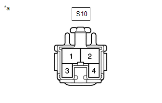
(a) Disconnect the stop light switch assembly connector. |
|
(b) Measure the voltage according to the value(s) in the table below.
Standard Voltage:
|
Tester Connection |
Condition |
Specified Condition |
|---|---|---|
|
S10-2 - Body ground |
Always |
11 to 14 V |
|
S10-4 - Body ground |
Ignition switch to ON |
11 to 14 V |
|
S10-4 - Body ground |
Ignition switch off |
Below 1 V |
| NG | |
REPAIR OR REPLACE HARNESS OR CONNECTOR |
|
|
4. |
INSPECT STOP LIGHT SWITCH ASSEMBLY |
(a) Remove the stop light switch assembly.
Click here
(b) Inspect the stop light switch assembly.
Click here
| NG | |
REPLACE STOP LIGHT SWITCH ASSEMBLY |
|
|
5. |
CHECK HARNESS AND CONNECTOR (ECM - STOP LIGHT SWITCH ASSEMBLY) |
(a) Disconnect the E21 ECM connector.
(b) Disconnect the S10 stop light switch assembly connector.
(c) Disconnect the S1 skid control ECU (brake actuator assembly) connector.
(d) Disconnect the S7 shift lock control unit connector.
(e) Remove the STOP relay from the engine room relay block.
(f) Measure the resistance according to the value(s) in the table below.
Standard Resistance:
|
Tester Connection |
Condition |
Specified Condition |
|---|---|---|
|
E21-11 (ST1-) - S10-3 |
Always |
Below 1 Ω |
|
E21-10 (STP) - S10-1 |
Always |
Below 1 Ω |
|
E21-11 (ST1-) or S10-3 - Body ground |
Always |
10 kΩ or higher |
|
E21-10 (STP) or S10-1 - Body ground |
Always |
10 kΩ or higher |
| OK | |
REPLACE ECM |
| NG | |
REPAIR OR REPLACE HARNESS OR CONNECTOR |
 Front Radar Sensor (C1A10)
DESCRIPTION
C1A10 is output when there is an internal malfunction in the millimeter wave
radar sensor assembly.
DTC No.
Detection Item
DTC Detection Condition
...
 Skid Control Buzzer Circuit (C1A4A)
DESCRIPTION
Based on dynamic radar cruise control system operation, the forward recognition
camera provides warnings to the driver by sounding the skid control buzzer.
DTC C1A4A is stored when a m ...
Other materials:
Portable Player cannot be Operated Using In-vehicle Device or Track Information
is not Displayed on In-vehicle Device
PROCEDURE
1.
CHECK USING ANOTHER "Bluetooth" AUDIO COMPATIBLE VEHICLE OF SAME MODEL
(a) Check if track information is displayed normally on another "Bluetooth" audio
compatible vehicle of the same model.
OK:
Track information is displayed no ...
Inspection
INSPECTION
PROCEDURE
1. INSPECT OIL CLEARANCE
(a) Using a micrometer and caliper gauge, measure the oil seal clearance.
Standard clearance:
0.021 to 0.043 mm (0.0008 to 0.0017 in.)
Maximum clearance:
0.07 mm (0.0028 in.)
If it is greater than the maximum, replace the vane pump assembly.
...
On-vehicle Inspection
ON-VEHICLE INSPECTION
PROCEDURE
1. INSPECT RADIATOR CAP SUB-ASSEMBLY
CAUTION:
Do not remove the radiator cap sub-assembly while the engine and radiator assembly
are still hot. Pressurized, hot engine coolant and steam may be released and cause
serious burns.
(a) Measure the valve opening pr ...
