
Toyota Tacoma (2015-2018) Service Manual: Blower Motor Circuit
DESCRIPTION
The blower motor with fan sub-assembly operates according to signals from the air conditioning amplifier assembly. The blower motor with fan sub-assembly speed signals are transmitted by changes in the duty ratio.
WIRING DIAGRAM
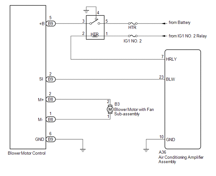
CAUTION / NOTICE / HINT
NOTICE:
Inspect the fuses for circuits related to this system before performing the following inspection procedure.
PROCEDURE
|
1. |
PERFORM ACTIVE TEST USING TECHSTREAM |
(a) Connect the Techstream to the DLC3.
(b) Turn the ignition switch to ON.
(c) Turn the Techstream on.
(d) Enter the following menus: Body Electrical / Air Conditioner / Active Test.
(e) According to the display on the Techstream, perform the Active Test.
Air Conditioner|
Tester Display |
Test Part |
Control Range |
Diagnostic Note |
|---|---|---|---|
|
Blower Motor |
Blower motor with fan sub-assembly |
Min.: 0, Max.: 31 |
- |
OK:
Blower motor with fan sub-assembly operates and blower motor speed changes.
|
Result |
Proceed to |
|---|---|
|
OK |
A |
|
NG (Blower motor with fan sub-assembly does not operate) |
B |
|
NG (Blower motor with fan sub-assembly operates but blower motor speed does not change) |
C |
| A | .gif) |
PROCEED TO NEXT SUSPECTED AREA SHOWN IN PROBLEM SYMPTOMS TABLE |
| C | |
GO TO STEP 8 |
|
.gif)
|
2. |
INSPECT BLOWER MOTOR WITH FAN SUB-ASSEMBLY |
(a) Remove the blower motor with fan sub-assembly (See page
.gif) )
)
(b) Inspect the blower motor with fan sub-assembly (See page
).
| NG | |
REPLACE BLOWER MOTOR WITH FAN SUB-ASSEMBLY |
|
|
3. |
INSPECT HTR RELAY |
(a) Remove the HTR relay.
(b) Inspect the HTR relay (See page ).
| NG | |
REPLACE HTR RELAY |
|
|
4. |
CHECK HARNESS AND CONNECTOR (HTR RELAY - POWER SOURCE CIRCUIT) |
(a) Remove the HTR relay.
(b) Measure the voltage according to the value(s) in the table below.
Standard Voltage:
|
Tester Connection |
Switch Condition |
Specified Condition |
|---|---|---|
|
HTR-5 - Body ground |
Always |
11 to 14 V |
|
HTR-1 - Body ground |
Ignition switch ON |
11 to 14 V |
| NG | |
REPAIR OR REPLACE HARNESS OR CONNECTOR |
|
|
5. |
CHECK HARNESS AND CONNECTOR (HTR RELAY - BLOWER MOTOR CONTROL AND AIR CONDITIONING AMPLIFIER ASSEMBLY) |
(a) Remove the HTR relay.
(b) Disconnect the B9 blower motor control connector.
(c) Disconnect the A36 air conditioning amplifier assembly connector.
(d) Measure the resistance according to the value(s) in the table below.
Standard Resistance:
|
Tester Connection |
Condition |
Specified Condition |
|---|---|---|
|
HTR-3 - B9-5 (+B) |
Always |
Below 1 Ω |
|
HTR-2 - A36-7 (HRLY) |
Always |
Below 1 Ω |
|
HTR-3 or B9-5 (+B) - Body ground |
Always |
10 kΩ or higher |
|
HTR-2 or A36-7 (HRLY) - Body ground |
Always |
10 kΩ or higher |
| NG | |
REPAIR OR REPLACE HARNESS OR CONNECTOR |
|
|
6. |
CHECK HARNESS AND CONNECTOR (BLOWER MOTOR CONTROL - BLOWER MOTOR WITH FAN SUB-ASSEMBLY AND BODY GROUND) |
(a) Disconnect the B3 blower motor with fan sub-assembly connector.
(b) Disconnect the B8 and B9 blower motor control connectors.
(c) Measure the resistance according to the value(s) in the table below.
Standard Resistance:
|
Tester Connection |
Condition |
Specified Condition |
|---|---|---|
|
B8-2 (M+) - B3-2 |
Always |
Below 1 Ω |
|
B8-1 (M-) - B3-1 |
Always |
Below 1 Ω |
|
B9-6 (GND) - Body ground |
Always |
Below 1 Ω |
|
B8-2 (M+) or B3-2 - Body ground |
Always |
10 kΩ or higher |
|
B8-1 (M-) or B3-1 - Body ground |
Always |
10 kΩ or higher |
| NG | |
REPAIR OR REPLACE HARNESS OR CONNECTOR |
|
|
7. |
CHECK HARNESS AND CONNECTOR (BLOWER MOTOR CONTROL - BLOWER MOTOR WITH FAN SUB-ASSEMBLY) |
(a) Disconnect the B9 blower motor control connector.
(b) Disconnect the A36 air conditioning amplifier assembly connector.
(c) Measure the resistance according to the value(s) in the table below.
Standard Resistance:
|
Tester Connection |
Condition |
Specified Condition |
|---|---|---|
|
B9-2 (SI) - A36-23 (BLW) |
Always |
Below 1 Ω |
|
B9-2 (SI) or A36-23 (BLW) - Body ground |
Always |
10 kΩ or higher |
| NG | |
REPAIR OR REPLACE HARNESS OR CONNECTOR |
|
|
8. |
CHECK AIR CONDITIONING AMPLIFIER ASSEMBLY |
|
(a) Remove the air conditioning amplifier assembly (See page
|
|
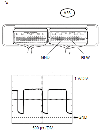
(b) Reconnect the A36 air conditioning amplifier assembly connector.
(c) Reconnect the B3 blower motor with fan sub-assembly connector.
(d) Reconnect the B8 and B9 blower motor control connector.
(e) Reinstall the HTR relay.
(f) Using an oscilloscope, check the waveform.
Measurement Condition|
Item |
Content |
|---|---|
|
Terminal No. (Symbol) |
A36-23 (BLW) - A36-10 (GND) |
|
Tester Range |
1 V/DIV., 500 μs/DIV. |
|
Condition |
Ignition switch ON Blower switch LO |
OK:
Waveform is as shown in the illustration.
HINT:
Waveform varies with the blower level.
Text in Illustration|
*a |
Component with harness connected (Air Conditioning Amplifier Assembly) |
| NG | |
REPLACE AIR CONDITIONING AMPLIFIER ASSEMBLY |
|
|
9. |
REPLACE BLOWER MOTOR CONTROL |
(a) Replace the blower motor control with a new or normally functioning one (See
page ).
(b) Operate the blower motor with fan sub-assembly to check that it functions properly.
OK:
Blower motor with fan sub-assembly operates normally.
| OK | |
END (BLOWER MOTOR CONTROL WAS DEFECTIVE) |
| NG | |
REPLACE AIR CONDITIONING AMPLIFIER ASSEMBLY |
 Pressure Sensor Circuit (B1423/23)
DESCRIPTION
This DTC is stored if refrigerant pressure on the high pressure side is extremely
low (176 kPa (1.8 kgf/cm2, 26 psi) or less) or extremely high (3140 kPa (32.0 kgf/cm2,
455 psi) or mo ...
 IG Power Source Circuit
DESCRIPTION
The main power source is supplied to the air conditioning amplifier assembly
when the ignition switch is turned to ON.
The power is used for operating the air conditioning amplifier as ...
Other materials:
Pattern Select Switch Power Mode Circuit
DESCRIPTION
The ECM memory contains the programs for the normal and PWR shift patterns.
By following the programs corresponding to the signals from the pattern select
switch assembly, park/neutral position switch and other various sensors, the ECM
switches the shift solenoid valves on and off, ...
Problem Symptoms Table
PROBLEM SYMPTOMS TABLE
HINT:
Use the table below to help determine the cause of problem symptoms.
If multiple suspected areas are listed, the potential causes of the symptoms
are listed in order of probability in the "Suspected Area" column of the
table. Check each sy ...
A/C ECU Vehicle Information Reading/Writing Processor Malfunction (B15F5)
DESCRIPTION
This DTC is stored when items controlled by the air conditioning amplifier assembly
cannot be customized via the audio and visual system vehicle customization screen.
HINT:
The air conditioning amplifier assembly controls the air conditioning system
related items that are customiz ...
