Toyota Tacoma (2015-2018) Service Manual: Automatic Transmission Assembly(for 2tr-fe)
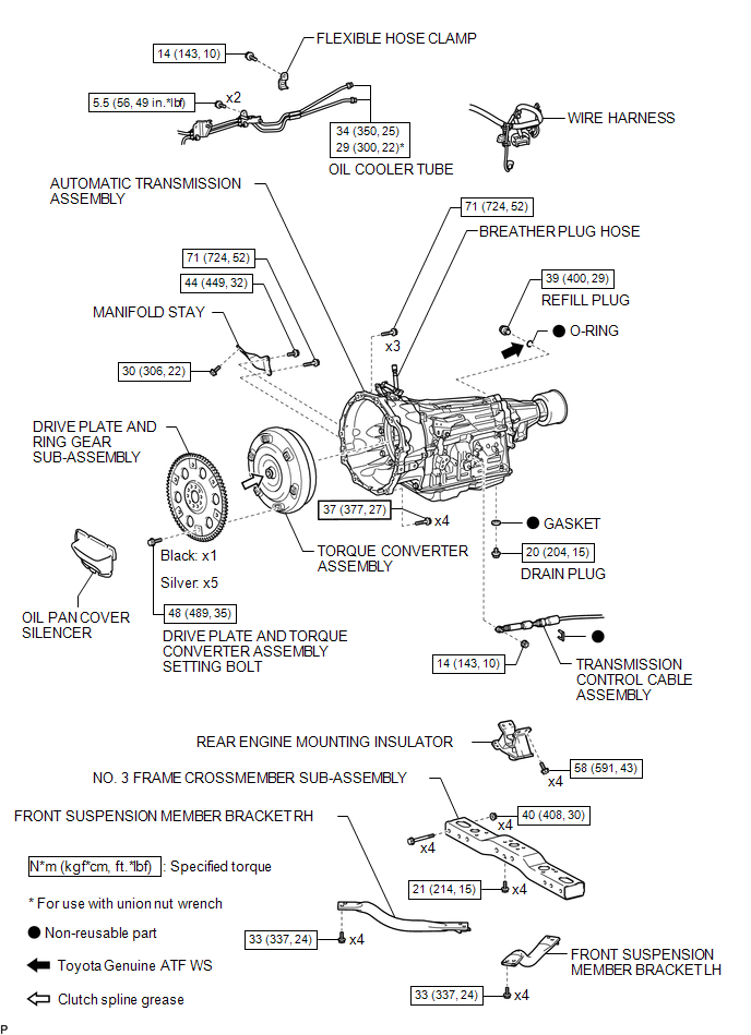
Components
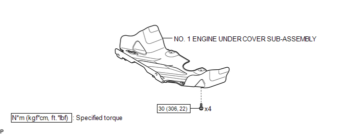
COMPONENTS
ILLUSTRATION
ILLUSTRATION
ILLUSTRATION
 Automatic Transmission Assembly(for 2gr-fks)
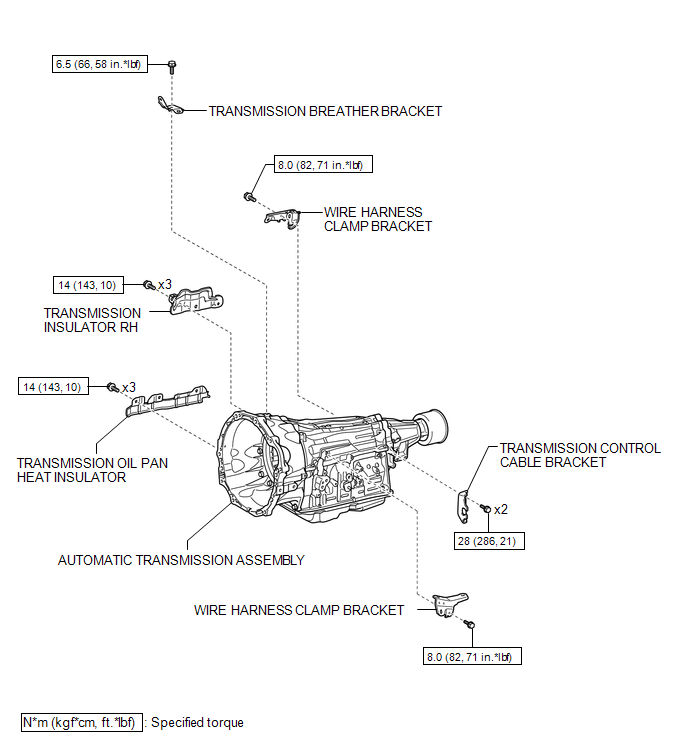
Components
COMPONENTS
ILLUSTRATION
ILLUSTRATION
ILLUSTRATION
...

Other materials:
Reassembly
REASSEMBLY
CAUTION / NOTICE / HINT
HINT:
Use the same procedure for the RH side and LH side.
The following procedure is for the LH side.
When installing a new front wheel opening extension pad or No. 1 front
wheel opening extension pad or No. 2 front wheel opening extension pa ...
Precaution
PRECAUTION
1. IGNITION SWITCH EXPRESSIONS
(a) The type of ignition switch used on this model differs according to the specifications
of the vehicle. The expressions listed in the table below are used in this section.
Expression
Ignition Switch (Position)
Engine ...
Vehicle Information Not Obtained (C1A02)
DESCRIPTION
When a new millimeter wave radar sensor assembly is installed, it receives vehicle
specification information (destination, steering wheel position, 2WD or 4WD, etc.)
from the main body ECU (multiplex network body ECU) and stores the information.
DTC C1A02 is stored when the millime ...
