Toyota Tacoma (2005–2015) Owners Manual: Active head restraints (Access Cab and Double Cab models only)
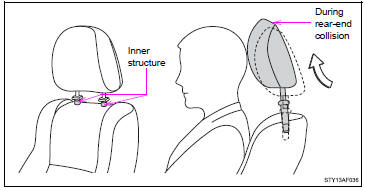
When the occupant’s back presses against the seatback during a rear-end collision, the head restraint moves slightly forward to help reduce the risk of whiplash on the seat occupant.
■Active head restraints
Even small forces applied to the seatback may cause the head restraint to move. Pushing up a locked head restraint forcibly may show the head restraint inner structure. These do not indicate problems.
■Waterproof and water-repellent seats (if equipped)
Waterproof and water-repellent seats are installed in your vehicle; however, the water-repellent effect does not last forever.
CAUTION
■Seat adjustment
●Be careful that the seat does not hit passengers or luggage.
●Do not recline the seat more than necessary when the vehicle is in motion to reduce the risk of sliding under the lap belt.
If the seat is too reclined, the lap belt may slide past the hips and apply restraint forces directly to the abdomen or your neck may contact the shoulder belt, increasing the risk of death or serious injury in the event of an accident.
●After adjusting the seat, make sure that the seat is locked in position.
■After returning the seatback to the upright position
Observe the following precautions. Failure to do so may result in death or serious injury.
●Make sure the seatback is securely locked.
●Check that the seat belts are not twisted or caught in the seatback.
●Arrange the seat belts in the proper positions for ready use.
■Caution while driving
●Vehicles with seatback table: Do not sit on or place anything on the folded seatback.
●Access Cab models only: Do not rest your foot on the press pedal behind the passenger seat.
 Folding passenger’s seat (vehicles with seatback table)
Pull the seatback angle adjusting lever and raise the seatback to its upright
position.
Pull the seatback folding lever and fold the seatback down. ...
 Rear seats (Access Cab and Double Cab models)
Access Cab models
The bottom cushion of the rear seats can be raised and lowered.
■ Before raising the bottom cushion
Stow the seat belt buckles.
This prevents the seat belt buckles from f ...
Other materials:
USB Device Malfunction (B1585)
DESCRIPTION
This DTC is stored when a malfunction occurs in a connected device.
DTC No.
DTC Detection Condition
Trouble Area
B1585
USB Device Malfunction
Non mass-storage class or incompatible protocol USB device
...
Unable to Lock Steering Wheel
DESCRIPTION
The steering lock actuator assembly activates the steering lock motor and moves
the lock bar into the steering column to lock the steering.
When the steering lock is operating, the steering may not lock when the lock
bar is not aligned with the lock hole of the steering column. In ...
Electrical Key Oscillator(for Rear Floor)
Components
COMPONENTS
ILLUSTRATION
Installation
INSTALLATION
PROCEDURE
1. INSTALL NO. 2 INDOOR ELECTRICAL KEY ANTENNA ASSEMBLY
(a) Engage the clamp to install the No. 2 indoor electrical key antenna assembly.
(b) Connect the connector.
2. INSTALL REAR CONSOLE BOX ASSEMBLY
(See page ...
