
Toyota Tacoma (2015-2018) Service Manual: Removal
REMOVAL
PROCEDURE
1. REMOVE MANUAL TRANSMISSION ASSEMBLY
(See page .gif) )
)
2. REMOVE CLUTCH RELEASE FORK SUB-ASSEMBLY
|
(a) Remove the clutch release fork sub-assembly with the clutch release bearing assembly from the manual transmission assembly. |
|
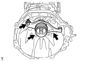
(b) Remove the release fork support from the manual transmission assembly.
|
(c) Remove the clip and clutch release bearing assembly from the clutch release fork sub-assembly. |
|
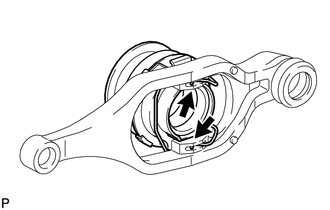
(d) Remove the clutch release fork collar from the clutch release fork sub-assembly.
(e) Remove the clutch release fork dust seal from the clutch release fork sub-assembly.
3. REMOVE CLUTCH COVER ASSEMBLY
|
(a) Put matchmarks on the clutch cover assembly and flywheel sub-assembly. Text in Illustration
|
|
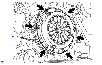
(b) Loosen each bolt one turn at a time until spring tension is released.
(c) Remove the 6 bolts and pull off the clutch cover assembly.
NOTICE:
Do not drop the clutch disc assembly.
4. REMOVE CLUTCH DISC ASSEMBLY
NOTICE:
Keep the lining part of the clutch disc assembly, the pressure plate and the surface of the flywheel sub-assembly away from oil and foreign matter.
 Inspection
INSPECTION
PROCEDURE
1. INSPECT CLUTCH DISC ASSEMBLY
NOTICE:
When replacing the clutch disc assembly, make sure to perform an inspection of
the flywheel sub-assembly and clutch cover assembly.
...
 Installation
INSTALLATION
PROCEDURE
1. INSTALL CLUTCH DISC ASSEMBLY
(a) Insert SST into the clutch disc assembly, and then install SST and the clutch
disc assembly together to the flywheel sub-assembly.
Tex ...
Other materials:
Data Signal Circuit between Navigation Receiver Assembly and Extension Module
DESCRIPTION
The stereo component tuner assembly sends the sound data signal or image data
signal from a device to the navigation receiver assembly via this circuit.
WIRING DIAGRAM
CAUTION / NOTICE / HINT
NOTICE:
After replacing the stereo component tuner assembly of vehicles subscribed to
...
Pressure Control Solenoid "G" Performance (Shift Solenoid Valve SL4) (P2808)
SYSTEM DESCRIPTION
The ECM uses the vehicle speed signal and signals from the transmission revolution
sensors (NT, SP2) to detect the actual gear (1st, 2nd, 3rd, 4th, 5th or 6th gear).
The ECM compares the actual gear with the shift schedule in the ECM memory to
detect mechanical problems of t ...
Cruise Control Input Processor (P160700)
DESCRIPTION
When the ECM determines that there is a malfunction, the ECM illuminates the
MIL and stores a DTC.
HINT:
When these DTCs are stored, the ECM cuts the current supplied to the throttle
motor and the throttle valve returns to the predetermined opening amount by the
return spring.
...
