Toyota Tacoma (2015-2018) Service Manual: 4WD ECU Malfunction (P163B)
DESCRIPTION
This DTC is output when a malfunction is detected in the 4 wheel drive control ECU internal circuit.
|
DTC No. |
Detection Item |
DTC Detection Condition |
Trouble Area |
|---|---|---|---|
|
P163B |
4WD ECU Malfunction |
|
|
WIRING DIAGRAM
.png)
CAUTION / NOTICE / HINT
NOTICE:
4WD specification:
- If P163B is detected, troubleshoot the TOUCH SELECT 2-4 AND HIGH-LOW system first.
PROCEDURE
|
1. |
CHECK HARNESS AND CONNECTOR (4 WHEEL DRIVE CONTROL ECU - DIFFERENTIAL LOCK COIL) |
(a) Turn the ignition switch off.
(b) Disconnect the F12 4 wheel drive control ECU connector.
(c) Disconnect the D28 differential lock coil connector.
(d) Measure the resistance according to the value(s) in the table below.
Standard Resistance:
|
Tester Connection |
Condition |
Specified Condition |
|---|---|---|
|
F12-1 (SL+) - D28-2 (SL+) |
Always |
Below 1 Ω |
|
F12-5 (SL-) - D28-1 (SL-) |
Always |
Below 1 Ω |
|
F12-1 (SL+) or D28-2 (SL+) - Body ground |
Always |
10 kΩ or higher |
|
F12-5 (SL-) or D28-1 (SL-) - Body ground |
Always |
10 kΩ or higher |
(e) Measure the voltage according to the value(s) in the table below.
Standard Voltage:
|
Tester Connection |
Switch Condition |
Specified Condition |
|---|---|---|
|
F12-1 (SL+) or D28-2 (SL+) - Body ground |
Ignition switch ON |
Below 1 V |
|
F12-5 (SL-) or D28-1 (SL-) - Body ground |
Ignition switch ON |
Below 1 V |
| NG | .gif) |
REPAIR OR REPLACE HARNESS AND CONNECTOR |
|
.gif)
|
2. |
INSPECT DIFFERENTIAL LOCK COIL |
(a) Turn the ignition switch off.
(b) Disconnect the D28 differential lock coil connector.
|
(c) Measure the resistance according to the value(s) in the table below. Standard Resistance:
|
|
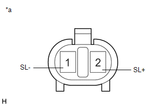
(d) Measure the voltage according to the value(s) in the table below.
Standard Voltage:
|
Tester Connection |
Switch Condition |
Specified Condition |
|---|---|---|
|
1 (SL-) or 2 (SL+) - Body ground |
Ignition switch ON |
Below 1 V |
| OK | |
REPLACE 4 WHEEL DRIVE CONTROL ECU |
| NG | |
REPLACE DIFFERENTIAL LOCK COIL |
 Rear Differential Lock Position SW Stuck ON (P17BC)
DESCRIPTION
This DTC is output when an ON malfunction of the differential lock indicator
switch is detected.
DTC No.
Detection Item
DTC Detection Condition
...
 ECU Power Source Circuit
WIRING DIAGRAM
CAUTION / NOTICE / HINT
NOTICE:
Inspect the fuses for circuits related to this system before performing the following
inspection procedure.
PROCEDURE
1.
...
Other materials:
Open in Driver Side Electrical Antenna Circuit (B27A1)
DESCRIPTION
The certification ECU (smart key ECU assembly) generates a request signal and
transmits the signal to the front door outside handle assembly LH [electrical key
antenna] at intervals of 0.25 seconds. For the front door outside handle assembly
LH [electrical key antenna] to detect w ...
Adjustment
ADJUSTMENT
CAUTION / NOTICE / HINT
HINT:
Centering bolts are used to mount the hood hinge and hood lock assembly.
The hood and hood lock assembly cannot be adjusted with the centering bolts
installed. Substitute the centering bolts with standard bolts when making
adjustments ...
Rear Door Courtesy Switch
Inspection
INSPECTION
PROCEDURE
1. INSPECT REAR DOOR COURTESY SWITCH
(a) Check the resistance.
(1) Measure the resistance using an ohmmeter, and check the results in accordance
with the value( s) in the table below.
Standard:
Tester Connection
Condition
S ...
