Toyota Tacoma (2015-2018) Service Manual: Wireless Door Lock Buzzer
Components
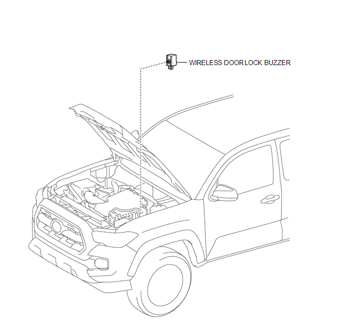
COMPONENTS
ILLUSTRATION
Removal
REMOVAL
PROCEDURE
1. REMOVE WIRELESS DOOR LOCK BUZZER
|
(a) Disconnect the connector. |
|
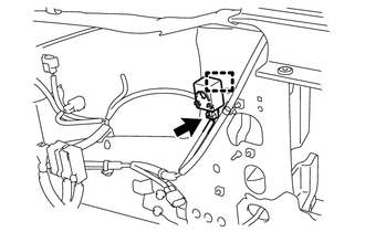
(b) Using a clip remover, disengage the clamp to remove the wireless door lock buzzer.
Installation
INSTALLATION
PROCEDURE
1. INSTALL WIRELESS DOOR LOCK BUZZER
(a) Engage the clamp to install the wireless door lock buzzer.
(b) Connect the connector.
 Unlock Warning Switch
Components
COMPONENTS
ILLUSTRATION
Inspection
INSPECTION
PROCEDURE
1. INSPECT UNLOCK WARNING SWITCH ASSEMBLY
(a) Check the resistance.
(1) Measure the resistance according to ...

Other materials:
On-vehicle Inspection
ON-VEHICLE INSPECTION
PROCEDURE
1. INSPECT SHIFT LEVER POSITION
(a) When moving the shift lever from P to each position with the ignition switch
ON and the brake pedal depressed, check that the shift lever moves smoothly and
correctly into position.
(b) Start the engine and check that the ve ...
Radio Antenna
Components
COMPONENTS
ILLUSTRATION
Removal
REMOVAL
PROCEDURE
1. REMOVE ROOF HEADLINING ASSEMBLY (for Double Cab)
(See page )
2. REMOVE ROOF HEADLINING ASSEMBLY (for Access Cab)
(See page )
3. REMOVE ANTENNA ASSEMBLY WITH HOLDER
(a) Disengage the 3 clamps.
(b) Remove the nut.
...
Bleeding
BLEEDING
CAUTION / NOTICE / HINT
NOTICE:
Wash off brake fluid immediately if it comes in contact with any painted surface.
HINT:
If any work is performed on the clutch system or if there is thought to be air
in the clutch lines, bleed air from the clutch hydraulic system.
PROCEDURE
1. FILL ...
