Toyota Tacoma (2005–2015) Owners Manual: What to do if...
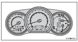
■ Instrument cluster
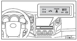
■ Center panel
■Warning lights
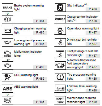
*1: Slip indicator comes on.
*2: The indicator flashes to indicate a malfunction.
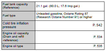
GAS STATION INFORMATION
 Camper information
This information has been prepared in accordance with regulation issued by
the National Highway Traffic Safety Administration of the U.S. Department of Transportation.
It provides the purchasers a ...
Other materials:
Installation
INSTALLATION
PROCEDURE
1. INSTALL AIR CONDITIONING UNIT ASSEMBLY
(a) Temporary install the air conditioning unit assembly.
(b) Insert the bracket hook into the holes of the reinforcement bracket, and
temporary install the instrument panel reinforcement assembly.
(c) Install the instrument p ...
Diagnostic Trouble Code Chart
DIAGNOSTIC TROUBLE CODE CHART
Blind Spot Monitor System
DTC Code
Detection Item
See page
C1A45
Vehicle Speed Sensor
C1A47
Steering Angle Sensor
C1AB0
Short ...
Installation
INSTALLATION
PROCEDURE
1. SET NO. 1 CYLINDER TO TDC/COMPRESSION
2. INSTALL CAMSHAFT TIMING GEAR BOLT
NOTICE:
There are different types of camshaft timing gear bolts. Make sure to check the
identification mark to determine the tightening torque.
*a
Identification Ma ...
