Toyota Tacoma (2015-2018) Service Manual: Vanity Light
Components
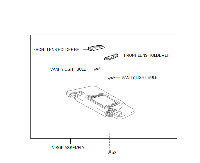
COMPONENTS
ILLUSTRATION
Removal
REMOVAL
CAUTION / NOTICE / HINT
HINT:
- Use the same procedures for the LH and RH side.
- The procedures listed below are for the LH side.
PROCEDURE
1. REMOVE VISOR ASSEMBLY
|
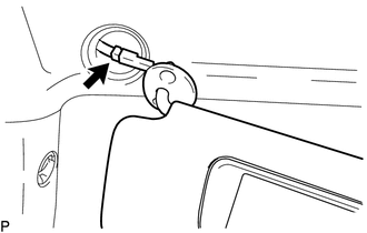
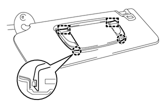
(a) Disengage the guide to separate the visor shaft. |
|
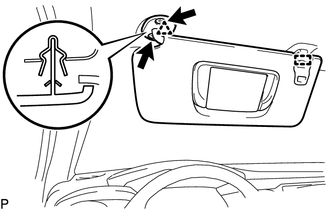
(b) Remove the 2 screws.
(c) Disengage the clip to separate the visor assembly.
|
(d) Disconnect the connector to remove the visor assembly. |
|
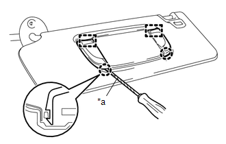
2. REMOVE VANITY LIGHT BULB
|
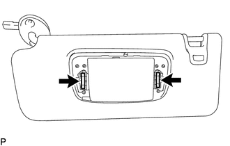
(a) Using a screwdriver with its tip wrapped in protective tape, disengage the 2 claws and 2 guides to remove the front lens holder LH and front lens holder RH. Text in Illustration
|
|
|
(b) Remove the 2 vanity light bulbs from the visor assembly. |
|
Installation
INSTALLATION
CAUTION / NOTICE / HINT
HINT:
- Use the same procedures for the LH and RH side.
- The procedures listed below are for the LH side.
PROCEDURE
1. INSTALL VANITY LIGHT BULB
(a) Install the 2 vanity light bulbs to the visor assembly.
|
(b) Engage the 2 guides and 2 claws to install the front lens holder LH and front lens holder RH. |
|
2. INSTALL VISOR ASSEMBLY
(a) Connect the connector.
(b) Engage the clip to install the visor assembly.
(c) Install the 2 screws.
(d) Engage the guide to install the visor shaft.
 Trailer Socket
Components
COMPONENTS
ILLUSTRATION
Removal
REMOVAL
PROCEDURE
1. REMOVE TRAILER SOCKET
(a) Disconnect the connector.
(b) Di ...

Other materials:
Installation
INSTALLATION
PROCEDURE
1. INSTALL CLUTCH PEDAL NO.1 CUSHION
(a) Install the clutch pedal No. 1 cushion to the clutch pedal sub-assembly.
2. INSTALL CLUTCH PEDAL SHAFT COLLAR
(a) Apply MP grease to the clutch pedal shaft collar.
Text in Illustration
MP grease
(b) ...
Brake Switch "A" Signal Compare Failure (P057162)
DESCRIPTION
When the brake pedal is depressed, stop light switch assembly sends a signal
to the ECM. Upon receiving the signal, the ECM cancels the cruise control system.
DTC Code
DTC Detection Condition
Trouble Area
MIL
Note
...
Check Bus 5 Line for Short to +B
DESCRIPTION
There may be a short circuit between one of the CAN bus lines and +B when no
resistance exists between terminal 15 (CA5H) of the central gateway ECU (network
gateway ECU) and terminal 16 (BAT) of the DLC3, or terminal 16 (CA5L) of the central
gateway ECU (network gateway ECU) and ...
