Toyota Tacoma (2015-2018) Service Manual: Transfer Case Rear Oil Seal
Components
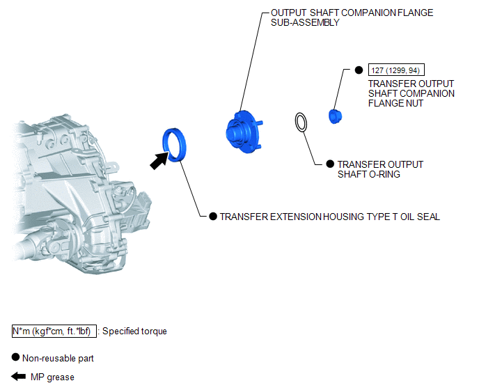
COMPONENTS
ILLUSTRATION
Replacement
REPLACEMENT
PROCEDURE
1. DRAIN TRANSFER OIL
.gif)
2. REMOVE PROPELLER WITH CENTER BEARING SHAFT ASSEMBLY
(See page )
3. REMOVE OUTPUT SHAFT COMPANION FLANGE SUB-ASSEMBLY
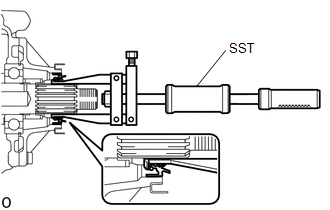
4. REMOVE TRANSFER EXTENSION HOUSING TYPE T OIL SEAL
|
(a) Using SST, remove the transfer extension housing type T oil seal. SST: 09308-00010 NOTICE: Be careful not to damage the transfer extension housing type T oil seal and extension housing contact surface. |
|
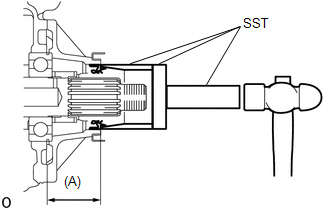
5. INSTALL TRANSFER EXTENSION HOUSING TYPE T OIL SEAL
(a) Coat the lip of a new transfer extension housing type T oil seal with MP grease.
|
(b) Using SST and a hammer, install the transfer extension housing type T oil seal as shown in the illustration. SST: 09631-12090 SST: 09950-60010 09951-00600 SST: 09950-70010 09951-07100 Drive in depth (A): 48.5 to 49.5 mm (1.910 to 1.948 in.) NOTICE: Be careful not to damage the transfer extension housing type T oil seal. |
|
6. INSTALL OUTPUT SHAFT COMPANION FLANGE SUB-ASSEMBLY
7. INSTALL PROPELLER WITH CENTER BEARING SHAFT ASSEMBLY
(See page )
8. ADD TRANSFER OIL
9. CHECK FOR TRANSFER OIL LEAK
 Transfer Case Front Oil Seal
Components
COMPONENTS
ILLUSTRATION
Replacement
REPLACEMENT
PROCEDURE
1. DRAIN TRANSFER OIL
2. SUPPORT TRANSMISSION ASSEMBLY
3. REMOVE NO. 3 FRAME CROSSMEMBER SUB-ASSEMBLY
4. ...
 Transfer Oil
On-vehicle Inspection
ON-VEHICLE INSPECTION
PROCEDURE
1. CHECK TRANSFER OIL
(a) Remove the filler plug and gasket.
Text in Illustration
*1
Fill ...
Other materials:
Road Test
ROAD TEST
PROBLEM SYMPTOM CONFIRMATION
HINT:
The dynamic radar cruise control system has 2 cruise control modes:
constant speed control mode and vehicle-to-vehicle distance control mode.
Vehicle-to-vehicle distance control mode is selected by default when
the dyna ...
System Diagram
SYSTEM DIAGRAM
Transmitting ECU
(Transmitter)
Receiving ECU
Signal
Communication Method
Airbag Sensor Assembly
ECM
Crash detection signal
CAN
Airbag Sensor Assembly
Com ...
Reporting safety defects for U.S. owners
If you believe that your vehicle has a defect which could cause a crash or could
cause injury or death, you should immediately inform the National Highway Traffic
Safety Administration (NHTSA) in addition to notifying Toyota Motor Sales, U.S.A.,
Inc. (Toll-free: 1-800-331-4331).
If NHTSA rece ...
