Toyota Tacoma (2015-2018) Service Manual: Tire Pressure Warning Receiver
Components
COMPONENTS
ILLUSTRATION
Removal
REMOVAL
PROCEDURE
1. SEPARATE ROOF HEADLINING ASSEMBLY (for Double Cab)
(See page .gif) )
)
2. SEPARATE ROOF HEADLINING ASSEMBLY (for Access Cab)
(See page )
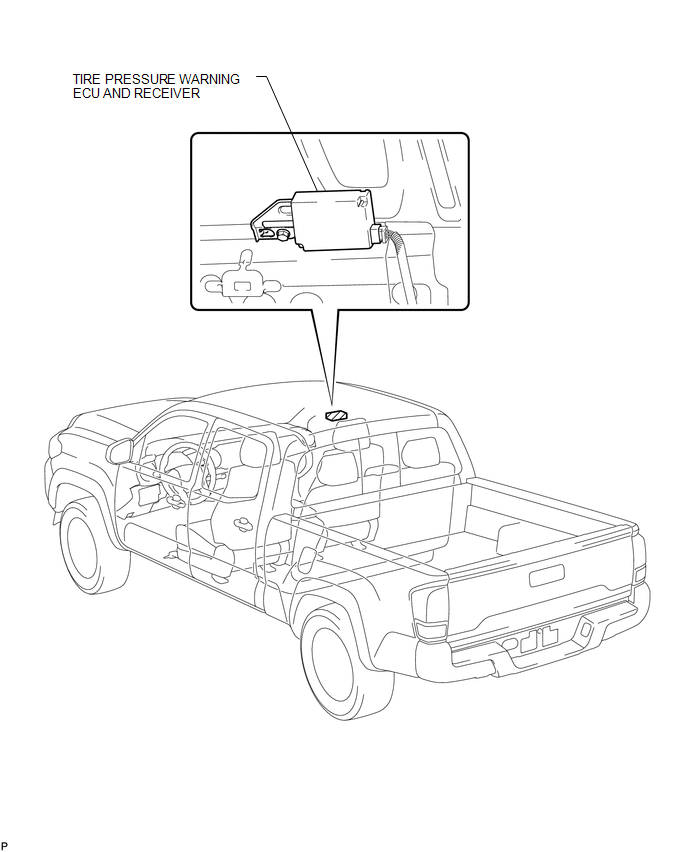
3. REMOVE TIRE PRESSURE WARNING ECU AND RECEIVER
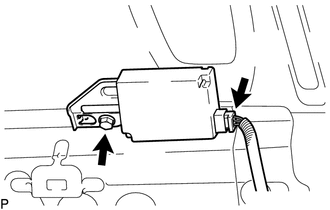
(a) Disconnect the connector.
(b) Remove the bolt and the tire pressure warning ECU and receiver.
Installation
INSTALLATION
PROCEDURE
1. INSTALL TIRE PRESSURE WARNING ECU AND RECEIVER
(a) Install the tire pressure warning ECU and receiver with the nut.
(b) Connect the connector.
2. INSTALL ROOF HEADLINING ASSEMBLY (for Double Cab)
(See page .gif) )
)
3. INSTALL ROOF HEADLINING ASSEMBLY (for Access Cab)
(See page )
4. REGISTRATION TRANSMITTER ID
(See page )
5. PERFORM INITIALIZATION
(See page )
 Precaution
PRECAUTION
1. REMOVAL AND INSTALLATION OF TIRE PRESSURE WARNING VALVE AND TRANSMITTER
(a) When installing a tire, make sure that the tire pressure warning valve and
transmitter does not interfere ...

Other materials:
Steering Angle Sensor Initialization Incomplete (C1439,C1445)
DESCRIPTION
The skid control ECU (master cylinder solenoid) acquires steering angle sensor
(spiral cable with sensor sub-assembly) zero point every time the ignition switch
is turned to ON and the vehicle is driven at 35 km/h (22 mph) or more for approximately
5 seconds. The ECU also stores t ...
Front Speed Sensor RH Malfunction (C1401,C1402)
DESCRIPTION
The speed sensor detects wheel speed and sends the appropriate signals to the
skid control ECU (brake actuator assembly). These signals are used for brake control.
The speed sensor rotors have rows of alternating N and S magnetic poles and their
magnetic fields change when the roto ...
Removal
REMOVAL
CAUTION / NOTICE / HINT
HINT:
Use the same procedure for the RH side and LH side.
The procedure listed below is for the LH side.
PROCEDURE
1. REMOVE FRONT WHEEL
2. REMOVE NO. 1 ENGINE UNDER COVER SUB-ASSEMBLY
3. SEPARATE FRONT STABILIZER LINK ASSEMBLY LH
...
