Toyota Tacoma (2015-2018) Service Manual: Removal
REMOVAL
CAUTION / NOTICE / HINT
HINT:
- Use the same procedure for the RH side and LH side.
- The procedure listed below is for the LH side.
PROCEDURE
1. REMOVE FRONT WHEEL
2. REMOVE NO. 1 ENGINE UNDER COVER SUB-ASSEMBLY
3. SEPARATE FRONT STABILIZER LINK ASSEMBLY LH
|
(a) Remove the nut and separate the front stabilizer link assembly LH from the steering knuckle. HINT: If the ball joint turns together with the nut, use a socket hexagon wrench 6 mm to hold the stud. |
|
.png)
4. SEPARATE FRONT STABILIZER LINK ASSEMBLY RH
HINT:
Use the same procedure for the RH side and LH side.
5. REMOVE FRONT NO. 1 STABILIZER BRACKET LH
.gif)
6. REMOVE FRONT NO. 1 STABILIZER BRACKET RH
HINT:
Use the same procedure for the RH side and LH side.
7. REMOVE FRONT STABILIZER BAR
8. SEPARATE TIE ROD END SUB-ASSEMBLY
9. REMOVE FRONT SHOCK ABSORBER WITH COIL SPRING
|
(a) Remove the bolt, nut and the washer on the lower side of the front shock absorber with coil spring. |
|
.png)
|
(b) Remove the 3 nuts on the upper side of the front shock absorber with coil spring. |
|
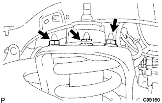
(c) Remove the front shock absorber with coil spring.
10. REMOVE FRONT SUPPORT TO FRONT SHOCK ABSORBER NUT
|
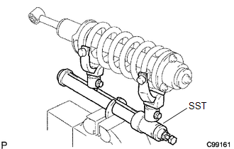
(a) Secure SST in a vise. SST: 09727-00060 SST: 09727-30021 09727-00010 09727-00031 |
|
|
(b) Attach the arm of SST to the diameter of the front coil spring. CAUTION:
|
|
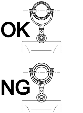
(c) Using SST, compress the front coil spring.
CAUTION:
- If the front coil spring bends during the compression, immediately stop the compression and reinstall SST.
- Do not compress the spring until the coil springs contact each other.
- Do not use an impact wrench. It will damage SST.
|
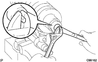
(d) Confirm that the front coil spring becomes free and while holding the shock absorber rod, remove the front support to front shock absorber nut. CAUTION: Do not remove the front support to front shock absorber nut when the front coil spring is not free. |
|
11. REMOVE FRONT SHOCK ABSORBER CUSHION RETAINER
12. REMOVE FRONT SHOCK ABSORBER NO. 1 CUSHION
13. REMOVE FRONT SUSPENSION SUPPORT SUB-ASSEMBLY
14. REMOVE FRONT SHOCK ABSORBER CUSHION RETAINER
15. REMOVE FRONT COIL SPRING
 Inspection
INSPECTION
PROCEDURE
1. INSPECT FRONT SHOCK ABSORBER ASSEMBLY
(a) Compress and extend the shock absorber rod and check that there is no abnormal
resistance or unusual sound during operation.
I ...
 Disposal
DISPOSAL
PROCEDURE
1. DISPOSE OF FRONT SHOCK ABSORBER ASSEMBLY
(a) Fully extend the shock absorber piston rod, and fix it at an angle in a vise
or similar tool.
(b) Using a drill or similar to ...
Other materials:
Front Airbag Sensor LH Circuit Malfunction (B1615/14)
DESCRIPTION
The front airbag sensor LH consists of parts such as the diagnostic circuit and
the frontal detection sensor.
When the airbag sensor assembly receives signals from the frontal deceleration
sensor, it determines whether or not the SRS should be activated.
DTC B1615/14 is set when a ...
On-vehicle Inspection
ON-VEHICLE INSPECTION
PROCEDURE
1. INSPECT CAMSHAFT TIMING GEAR BOLT
(a) Remove the camshaft timing oil control solenoid assembly (See page
).
(b) Check that the plunger strokes when the plunger in the center of
the camshaft timing gear bolt is pressed.
Standard stroke:
4 ...
Meter Illumination does not Dim at Night
DESCRIPTION
In this circuit, the combination meter assembly auto dimmer signals from the
main body ECU using the CAN communication system (CAN V1 Bus). When the combination
meter assembly an auto dimmer signal, it dims the meter illumination (warning and
indicator lights). The main body ECU ( ...
