Toyota Tacoma (2015-2018) Service Manual: Reassembly
REASSEMBLY
PROCEDURE
1. INSTALL REAR BUMPER SIDE STAY LH
|
(a) Install the rear bumper side stay LH with the 2 bolts. Torque: 30 N·m {306 kgf·cm, 22 ft·lbf} |
|
.png)
2. INSTALL REAR BUMPER SIDE STAY RH
HINT:
Use the same procedure as for the LH side.
3. INSTALL NO. 6 FLOOR WIRE
|
(a) Engage the wire harness clamps to install the No. 6 floor wire. Text in Illustration
|
|
(b) Install 2 new adhesive tapes.
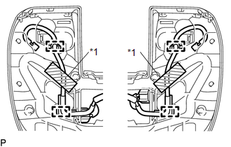
4. INSTALL BLIND SPOT MONITOR SENSOR LH (w/ Blind Spot Monitor)
|
(a) Install the blind spot monitor sensor LH with the 3 nuts. Torque: 9.0 N·m {92 kgf·cm, 80 in·lbf} |
|
.png)
(b) Connect the connector.
5. INSTALL BLIND SPOT MONITOR SENSOR RH (w/ Blind Spot Monitor)
HINT:
Use the same procedure as for the LH side.
6. INSTALL NO. 1 ULTRASONIC SENSOR (w/ Clearance Sonar System)
.gif)
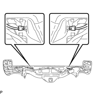
7. INSTALL REAR BUMPER EXTENSION LH
(a) w/ Clearance Sonar System:
|
(1) Connect the connector. Text in Illustration
|
|
(b) Install the rear bumper extension LH.
(c) Install the clamp.
(d) Install the 5 clips.
8. INSTALL REAR BUMPER EXTENSION RH
HINT:
Use the same procedure as for the LH side.
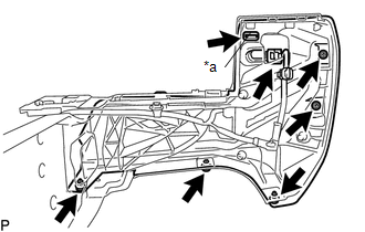
9. INSTALL REAR BUMPER PLATE
(a) Engage the 6 guides to install the rear bumper plate.
.png) Text in Illustration
Text in Illustration
|
*a |
Wire Harness Clamp |
*b |
Guide |
(b) Install the 10 bolts.
Torque:
30 N·m {306 kgf·cm, 22 ft·lbf}
(c) Engage the wire harness clamps.
10. INSTALL NO. 1 ULTRASONIC SENSOR (w/ Clearance Sonar System)
11. INSTALL REAR BUMPER PAD SUB-ASSEMBLY
|
(a) Engage the 2 claws to install the license plate light lens. HINT: Use the same procedure for the RH side and LH side. |
|
.png)
(b) w/ Clearance Sonar System:
(1) Connect the 2 connectors.
.png)
(2) Engage the 14 claws to install the rear bumper pad sub-assembly.
(3) Install the 3 clips.
(c) w/o Clearance Sonar System:
(1) Engage the 14 claws to install the rear bumper pad sub-assembly.
.png)
(2) Install the 3 clips.
|
(d) Connect the connector to install the license plate light socket. HINT: Use the same procedure for the RH side and LH side. |
|
.png)
|
(e) Install the 2 license plate light assemblies. |
|
12. INSTALL CONNECTOR COVER
|
(a) Engage the 2 clips to install the connector cover. |
|
.png)
 Disassembly
DISASSEMBLY
PROCEDURE
1. REMOVE CONNECTOR COVER
(a) Disengage the 2 clips to remove the connector cover.
2. REMOVE REAR BUMPER PAD SUB-ASSEMBLY ...
 Installation
INSTALLATION
PROCEDURE
1. INSTALL REAR BUMPER ASSEMBLY
(a) Using an engine lifter or equivalent, engage the 2 pins to install the rear
bumper assembly as shown in the illustration.
Text in Illu ...
Other materials:
Inspection
INSPECTION
PROCEDURE
1. INSPECT AIR CONDITIONING CONTROL ASSEMBLY
(a) Check the blower switch resistance.
(1) Measure the resistance according to the value(s) in the table below.
Text in Illustration
*a
Component without harness connected
...
CD cannot be Ejected
PROCEDURE
1.
CHECK OPERATION
(a) Press the disc eject switch of the radio and display receiver assembly for
5 seconds or more and check that the CD is ejected.
OK:
CD is ejected.
NG
REPLACE RADIO AND DISPLAY RECEIVER ASSEMBLY
...
Dtc Check / Clear
DTC CHECK / CLEAR
CHECK FOR DTC
(a) Connect the Techstream to the DLC3.
(b) Turn the ignition switch to ON.
(c) Turn the Techstream on.
(d) Enter the following menus: Body Electrical / Central Gateway / Trouble Codes.
(e) Read the DTCs.
CLEAR DTC
(a) Connect the Techstream to the DLC3.
(b) ...
