Toyota Tacoma (2015-2018) Service Manual: Terminals Of Ecu
TERMINALS OF ECU
1. CHECK MAIN BODY ECU (MULTIPLEX NETWORK BODY ECU)
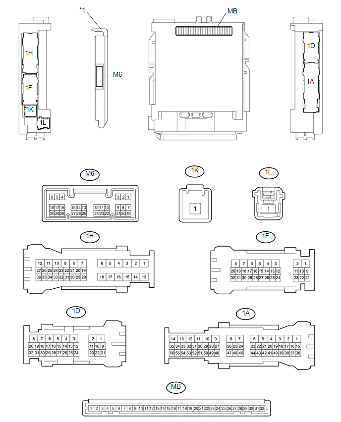 Text in Illustration
|
*1 |
Main Body ECU (Multiplex Network Body ECU) |
- |
- |
(a) Disconnect the driver side junction block and main body ECU (multiplex network body ECU) connectors.
(b) Measure the voltage on the wire harness side connector according to the value(s) in the table below.
|
Terminal No. (Symbols) |
Wiring Color |
Terminal Description |
Condition |
Specified Condition |
|---|---|---|---|---|
|
MB-31 (BECU) - Body ground |
- |
Battery power supply |
Always |
11 to 14 V |
If the result is not as specified, there may be a malfunction in the wire harness.
(c) Measure the resistance on the wire harness side connector according to the value(s) in the table below.
|
Terminal No. (Symbols) |
Wiring Color |
Terminal Description |
Condition |
Specified Condition |
|---|---|---|---|---|
|
MB-11 (GND1) - Body ground |
- |
Ground |
Always |
Below 1 Ω |
If the result is not as specified, there may be a malfunction in the wire harness.
(d) Reconnect the driver side junction block and main body ECU (multiplex network body ECU) connectors.
(e) Measure the voltage and check for pulses according to the value(s) in the table below.
|
Terminal No. (Symbols) |
Wiring Color |
Terminal Description |
Condition |
Specified Condition |
|---|---|---|---|---|
|
MB-30 (ACC) - Body ground |
- |
ACC power supply |
Ignition switch ACC |
11 to 14 V |
|
Ignition switch off |
Below 1 V |
|||
|
MB-32 (IG) - Body ground |
- |
IG power supply |
Ignition switch ON |
11 to 14 V |
|
Ignition switch off |
Below 1 V |
|||
|
M6-1 (DIM) - Body ground |
Y - Body ground |
Dimmer relay output |
Dimmer switch in low position |
11 to 14 V |
|
Dimmer switch in high or high flash position |
Below 1 V |
|||
|
1F-28 - Body ground |
W - Body ground |
Headlight relay drive output |
Light control switch in head position |
Below 1 V |
|
Light control switch not in head position |
11 to 14 V |
|||
|
1F-30 - Body ground*1 |
R - Body ground |
Daytime running light system drive output |
Daytime running light system operating |
Below 1 V |
|
Daytime running light system not operating |
11 to 14 V |
|||
|
M6-24 (HU) - Body ground |
BE - Body ground |
Dimmer switch high position signal input |
Dimmer switch in high position |
Below 1 V |
|
Dimmer switch not in high position |
11 to 14 V or pulse generation |
|||
|
M6-10 (HF) - Body ground |
SB - Body ground |
Dimmer switch high flash position signal input |
Dimmer switch in high flash position |
Below 1 V |
|
Dimmer switch not in high flash position |
11 to 14 V or pulse generation |
|||
|
M6-17 (AHBI) - Body ground*5 |
R - Body ground |
Auto high beam main switch signal input |
Auto high beam main switch on |
Below 1 V |
|
Auto high beam main switch off |
11 to 14 V |
|||
|
M6-22 (TAIL) - Body ground |
G - Body ground |
Light control switch tail position signal input |
Light control switch in tail or head position |
Below 1 V |
|
Ignition switch off, light control switch not in tail or head position |
11 to 14 V or pulse generation |
|||
|
M6-12 (HEAD) - Body ground |
Y - Body ground |
Light control switch head position input |
Light control switch in head position |
Below 1 V |
|
Ignition switch off, light control switch not in head position |
11 to 14 V or pulse generation |
|||
|
M6-8 (A) - Body ground*2, *4 |
W - Body ground |
Light control switch AUTO position signal input |
Light control switch in AUTO position |
Below 1 V |
|
Ignition switch off, light control switch not in AUTO position |
11 to 14 V or pulse generation |
|||
|
M6-26 (FFOG) - Body ground*3 |
L - Body ground |
Fog light switch front position input |
Fog light switch in front position |
Below 1 V |
|
Ignition switch off, fog light switch off |
11 to 14 V or pulse generation |
|||
|
M6-19 (CLTB)*4 - M6-21 (CLTE)*4 |
P - R |
Automatic light control sensor power supply output |
Ignition switch off |
Below 1 V |
|
Ignition switch ON |
11 to 14 V |
|||
|
M6-20 (CLTS)*4 - Body ground |
GR - Body ground |
Automatic light control sensor signal input |
Ignition switch off |
Below 1 V |
|
Ignition switch ON |
Communication waveform generation (See waveform 1) |
|||
|
1F-27 - Body ground*3 |
BE - Body ground |
Front fog light drive output |
Light control switch in tail or head position, fog light switch in front position |
Below 1 V |
|
Light control switch in tail or head position, fog light switch off |
11 to 14 V |
|||
|
1H-36 - Body ground |
P - Body ground |
Rear door courtesy light switch LH input |
Rear door LH open |
Below 1 V |
|
Rear door LH closed |
Pulse generation |
|||
|
1D-30 - Body ground |
V - Body ground |
Rear door courtesy light switch RH input |
Rear door RH open |
Below 1 V |
|
Rear door RH closed |
Pulse generation |
|||
|
M6-6 (FLCY) - Body ground |
Y - Body ground |
Front door courtesy light switch LH input |
Front door LH open |
Below 1 V |
|
Front door LH closed |
pulse generation |
|||
|
M6-27 (FRCY) - Body ground |
LG - Body ground |
Front door courtesy light switch RH input |
Front door RH open |
Below 1 V |
|
Front door RH closed |
pulse generation |
|||
|
1H-27 - Body ground |
L - Body ground |
Rear door unlock detection switch LH input |
Rear door LH locked |
Pulse generation |
|
Rear door LH or rear door RH unlocked |
Below 1 V |
|||
|
1A-41 - Body ground |
Y - Body ground |
Rear door unlock detection switch RH input |
Rear door RH locked |
Pulse generation |
|
Rear door LH or rear door RH unlocked |
Below 1 V |
|||
|
1D-11 - Body ground |
P - Body ground |
Front door unlock detection switch LH input |
Front door LH locked |
Pulse generation |
|
Front door LH unlocked |
Below 1 V |
|||
|
1D-24 - Body ground |
GR - Body ground |
Front door unlock detection switch RH input |
Front door RH locked |
Pulse generation |
|
Front door RH unlocked |
Below 1 V |
- *1: LED Type Daytime Running Light and Parking Light
- *2: w/ Daytime Running Light
- *3: w/ Fog Light
- *4: w/ Automatic Light Control
- *5: w/ Automatic High Beam System
(1) If the result is not as specified, the main body ECU (multiplex network body ECU) or driver side junction block may be malfunctioning.
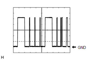 Waveform 1
|
Item |
Content |
|---|---|
|
Tool setting |
2 V/DIV., 10 ms./DIV. |
|
Vehicle condition |
Ignition switch ON, automatic light control system operating |
HINT:
The communication waveform changes according to the surrounding brightness.
 Problem Symptoms Table
PROBLEM SYMPTOMS TABLE
HINT:
Use the table below to help determine the cause of the problem symptom.
The potential causes of the symptoms are listed in order of probability
in the &q ...
 Light Sensor Circuit Malfunction (B1244)
DESCRIPTION
This DTC is output when a failure of the automatic light control sensor circuit
is detected.
DTC Code
DTC Detection Condition
Trouble Area
...
Other materials:
High Power Supply Voltage Malfunction (C1417)
DESCRIPTION
If a malfunction is detected in the power supply circuit, the skid control ECU
(brake actuator assembly) stores this DTC and the fail-safe function prohibits ABS
operation.
This DTC is stored when the +BS terminal voltage deviates from the DTC detection
condition due to a malfunc ...
Rear Airbag Sensor LH Circuit Malfunction (B1635/24)
DESCRIPTION
The airbag sensor LH consists of parts such as the safing sensor, the diagnostic
circuit and the lateral deceleration sensor.
When the airbag sensor assembly receives signals from the lateral deceleration
sensor, it determines whether or not the SRS should be activated.
DTC B1635/ ...
Blind Spot Monitor Slave Module Beam Axis Inspection Incomplete (C1ABC)
DESCRIPTION
This DTC is stored when a beam axis inspection has not been performed for the
blind spot monitor sensor RH.
HINT:
This DTC is always stored after replacing a blind spot monitor sensor. The purpose
of this DTC is to ensure that beam axis inspection is performed. Completing the
be ...
