Toyota Tacoma (2015-2018) Service Manual: High Power Supply Voltage Malfunction (C1417)
DESCRIPTION
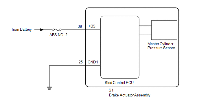
If a malfunction is detected in the power supply circuit, the skid control ECU (brake actuator assembly) stores this DTC and the fail-safe function prohibits ABS operation.
This DTC is stored when the +BS terminal voltage deviates from the DTC detection condition due to a malfunction in the power supply or charging circuit such as the battery or generator circuit, etc.
The DTC is canceled when the +BS terminal voltage returns to normal.
|
DTC No. |
Detection Item |
DTC Detection Condition |
Trouble Area |
|---|---|---|---|
|
C1417 |
High Power Supply Voltage Malfunction |
Either of the following is detected:
|
|
HINT:
DTC will be output when conditions for either of the patterns in the table above are met.
WIRING DIAGRAM
CAUTION / NOTICE / HINT
NOTICE:
- When replacing the skid control ECU (brake actuator assembly), perform
zero point calibration and store system information (See page
.gif) ).
).
- Inspect the fuses for circuits related to this system before performing the following inspection procedure.
PROCEDURE
|
1. |
INSPECT BATTERY |
(a) Check the battery voltage.
Standard voltage:
11 to 14 V
| NG | .gif) |
CHECK OR REPLACE CHARGING SYSTEM OR BATTERY |
|
.gif)
|
2. |
CHECK TERMINAL VOLTAGE (+BS, GND1 TERMINAL) |
(a) Turn the ignition switch off.
(b) Make sure that there is no looseness at the locking part and the connecting part of the connectors.
|
(c) Disconnect the skid control ECU (brake actuator assembly) connector. |
|
(d) Measure the voltage according to the value(s) in the table below.
Standard Voltage:
|
Tester Connection |
Condition |
Specified Condition |
|---|---|---|
|
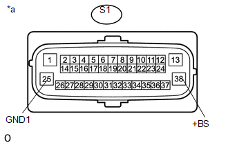
S1-38 (+BS) - Body ground |
Always |
11 to 14 V |
|
S1-38 (+BS) - S1-25 (GND1) |
Always |
11 to 14 V |
|
*a |
Front view of wire harness connector (to Skid Control ECU [Brake Actuator Assembly]) |
| NG | |
REPAIR OR REPLACE HARNESS OR CONNECTOR (+BS, GND1 CIRCUIT) |
|
|
3. |
RECONFIRM DTC |
(a) Reconnect the S1 skid control ECU (brake actuator assembly) connector.
(b) Clear the DTCs (See page
).
(c) Turn the ignition switch off.
(d) Start the engine.
(e) Perform a road test.
(f) Check if the same DTC is recorded (See page
).
|
Result |
Proceed to |
|---|---|
|
DTC C1417 is not output |
A |
|
DTC C1417 is output |
B |
| A | |
USE SIMULATION METHOD TO CHECK |
| B | |
REPLACE BRAKE ACTUATOR ASSEMBLY |
 Rear Speed Sensor RH Output Malfunction (C1415,C1416)
DESCRIPTION
Refer to DTCs C1403 and C1404 (See page ).
DTC No.
Detection Item
DTC Detection Condition
Trouble Area
C1415
Rear ...
 Acceleration Sensor Internal Circuit (C1419,C1435)
DESCRIPTION
The skid control ECU (brake actuator assembly) receives signals from the yaw
rate and acceleration sensor (airbag sensor assembly) via the CAN communication
system.
The airbag sensor ...
Other materials:
If your vehicle overheats
The following may indicate that your vehicle is overheating.
● The needle of the engine coolant temperature gauge (→P. 155) enters the red
zone or a loss of engine power is experienced.
(For example, the vehicle speed does not increase.) ● Steam comes out from under
the hood. ...
Short to GND in Outer Mirror Indicator(Master) (C1AB2)
DESCRIPTION
This DTC is stored when the blind spot monitor sensor LH detects a ground short
in the blind spot monitor indicator LH.
DTC Code
DTC Detection Condition
Trouble Area
C1AB2
With the blind spot monitor main switch assembly (w ...
Lost Communication with Meter (B1324)
DESCRIPTION
This DTC is stored when a communication error occurs between the radio and display
receiver assembly and combination meter assembly.
DTC No.
DTC Detection Condition
Trouble Area
B1324
After the radio and display receiver as ...
