Toyota Tacoma (2015-2018) Service Manual: Light Sensor Circuit Malfunction (B1244)
DESCRIPTION
This DTC is output when a failure of the automatic light control sensor circuit is detected.
|
DTC Code |
DTC Detection Condition |
Trouble Area |
|---|---|---|
|
B1244 |
When either condition below is met:
|
|
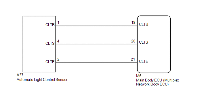
WIRING DIAGRAM
CAUTION / NOTICE / HINT
NOTICE:
If the main body ECU (multiplex network body ECU) is replaced, refer to Registration
(See page .gif) ).*1
).*1
- *1: w/ Smart Key System
PROCEDURE
|
1. |
CHECK FOR DTC |
(a) Clear the DTC (See page ).
(b) Recheck for DTC (See page ).
OK:
DTC B1244 is not output.
| OK | .gif) |
USE SIMULATION METHOD TO CHECK |
|
.gif)
|
2. |
READ VALUE USING TECHSTREAM (LIGHT SENSOR ILLUMINANCE) |
(a) Connect the Techstream to the DLC3.
(b) Turn the ignition switch to ON.
(c) Turn the Techstream on.
(d) Enter the following menus: Body Electrical / Main Body / Data List.
(e) According to the display on the Techstream, read the Data List.
Main Body|
Tester Display |
Measurement Item/Range |
Normal Condition |
Diagnostic Note |
|---|---|---|---|
|
Light Sensor Illuminance |
Light control sensor illuminance / 0 to 8191 lx |
Value is output according to ambient light level |
- |
OK:
Output illuminance is as shown in table above.
| OK | |
REPLACE MAIN BODY ECU (MULTIPLEX NETWORK BODY ECU) |
|
|
3. |
CHECK MAIN BODY ECU (MULTIPLEX NETWORK BODY ECU) (LIGHT CONTROL SENSOR VOLTAGE) |
|
(a) Disconnect the ECU connector. |
|
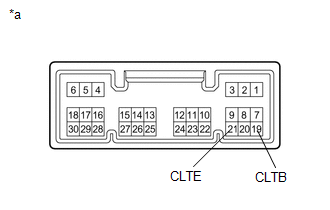
(b) Measure the voltage according to the value(s) in the table below.
Standard voltage:
|
Tester Connection |
Switch Condition |
Specified Condition |
|---|---|---|
|
19 (CLTB) - 21 (CLTE) |
Ignition switch ON |
11 to 14 V |
|
Ignition switch OFF |
Below 1 V |
|
*a |
Component without harness connected (Main Body ECU (Multiplex Network Body ECU)) |
| NG | |
REPLACE MAIN BODY ECU (MULTIPLEX NETWORK BODY ECU) |
|
|
4. |
CHECK HARNESS AND CONNECTOR (MAIN BODY ECU (MULTIPLEX NETWORK BODY ECU) - AUTOMATIC LIGHT CONTROL SENSOR) |
(a) Disconnect the M6 main body ECU (multiplex network body ECU) connector.
(b) Disconnect the A37 automatic light control sensor connector.
(c) Measure the resistance according to the value(s) in the table below.
Standard resistance:
|
Tester Connection |
Condition |
Specified Condition |
|---|---|---|
|
M6-19 (CLTB) - A37-1 (CLTB) |
Always |
Below 1 Ω |
|
M6-20 (CLTS) - A37-4 (CLTS) |
||
|
M6-21 (CLTE) - A37-2 (CLTE) |
||
|
M6-19 (CLTB) - Body ground |
Always |
10 kΩ or higher |
|
M6-20 (CLTS) - Body ground |
||
|
M6-21 (CLTE) - Body ground |
| OK | |
REPLACE AUTOMATIC LIGHT CONTROL SENSOR |
| NG | |
REPAIR OR REPLACE HARNESS OR CONNECTOR |
 Terminals Of Ecu
TERMINALS OF ECU
1. CHECK MAIN BODY ECU (MULTIPLEX NETWORK BODY ECU)
Text in Illustration
*1
Main Body ECU (Multiplex Network Body ECU)
-
-
(a ...
 Data List / Active Test
DATA LIST / ACTIVE TEST
1. DATA LIST
HINT:
Using the Techstream to read the Data List allows values or states of switches,
sensors, actuators and other items to be read without removing any parts ...
Other materials:
Customize Parameters
CUSTOMIZE PARAMETERS
1. CUSTOMIZE SMART KEY SYSTEM (for Entry Function)
HINT:
The following items can be customized.
NOTICE:
When the customer requests a change in a function, first make sure that
the function can be customized.
Record the current settings before customizing.
...
On-vehicle Inspection
ON-VEHICLE INSPECTION
PROCEDURE
1. INSPECT OCCUPANT DETECTION ECU (for Vehicle not Involved in Collision)
(a) Perform a diagnostic system check (See page
).
2. INSPECT OCCUPANT DETECTION ECU (for Vehicle Involved in Collision)
(a) Perform a diagnostic system check (See page
).
(b) Even if ...
Data List / Active Test
DATA LIST / ACTIVE TEST
1. DATA LIST
HINT:
Using the Techstream to read the Data List allows the values or states of switches,
sensors, actuators and other items to be read without removing any parts. This non-intrusive
inspection can be very useful because intermittent conditions or signals ...
