Toyota Tacoma (2015-2018) Service Manual: Terminals Of Ecu
TERMINALS OF ECU
NOTICE:
- DTCs may be output when connectors are disconnected during inspection. Therefore, be sure to clear the DTCs using the Techstream once the inspection has been completed.
- Do not apply excessive force to the f5 forward recognition camera connector.
CHECK FORWARD RECOGNITION CAMERA
(a) Disconnect the forward recognition camera connector.

|
*a |
Front view of wire harness connector (to Forward Recognition Camera) |
- |
- |
(b) Measure the voltage and resistance according to the value(s) in the table below.
|
Terminal No. (Symbol) |
Wiring Color |
Terminal Description |
Condition |
Specified Condition |
|---|---|---|---|---|
|
F46-7 (IGB) - F46-10 (GND) |
BE - W-B |
Power source |
Ignition switch ON |
11 to 14 V |
|
Ignition switch off |
Below 1 V |
|||
|
F46-10 (GND) - Body ground |
W-B - Body ground |
Ground |
Always |
Below 1 Ω |
(c) Reconnect the forward recognition camera connector.

|
*a |
Component with harness connected (Forward Recognition Camera) |
- |
- |
(d) Measure the voltage according to the value(s) in the table below.
|
Terminal No. (Symbol) |
Wiring Color |
Terminal Description |
Condition |
Specified Condition |
|---|---|---|---|---|
|
F46-1 (HTR) - F46-10 (GND) |
R - W-B |
Camera heater (forward recognition hood) operation signal |
Ignition switch ON, camera heater (forward recognition hood) not operating |
11 to 14 V |
|
Ignition switch ON, camera heater (forward recognition hood) operating |
0 to 1.5 V |
|||
|
F46-8 (BZ) - F46-10 (GND) |
L - W-B |
Skid control buzzer |
Ignition switch ON, skid control buzzer not operating |
11 to 14 V |
|
Ignition switch ON, skid control buzzer operating |
0 to 1.5 V |
(e) Check for pulses according to the value(s) in the table below.
HINT:
If the waveform is not similar to that shown in the illustration, a malfunction of a CAN bus line, terminating resistor, or the forward recognition camera is suspected.
|
Terminal No. (Symbol) |
Wiring Color |
Terminal Description |
Condition |
Specified Condition |
|---|---|---|---|---|
|
F46-5 (CA1P) - F46-10 (GND) |
L - W-B |
CAN communication signal |
Ignition switch ON |
Pulse generation (See waveform 1) |
|
F46-11 (CA1N) - F46-10 (GND) |
W - W-B |
CAN communication signal |
Ignition switch ON |
Pulse generation (See waveform 2) |
|
F46-6 (CANH) - F46-10 (GND) |
B - W-B |
CAN communication signal |
Ignition switch ON |
Pulse generation (See waveform 1) |
|
F46-12 (CANL) - F46-10 (GND) |
W - W-B |
CAN communication signal |
Ignition switch ON |
Pulse generation (See waveform 2) |
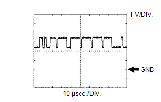
(1) Waveform 1
|
Item |
Content |
|---|---|
|
Terminal Name |
Between F46-5 (CA1P) and F46-10 (GND) Between F46-6 (CANH) and F46-10 (GND) |
|
Tester Range |
1 V/DIV., 10 ÎĽsec./DIV. |
|
Condition |
Ignition switch ON |
HINT:
The waveform varies depending on the CAN communication signal.
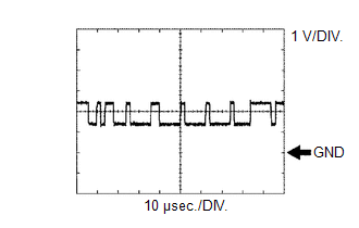
(2) Waveform 2
|
Item |
Content |
|---|---|
|
Terminal Name |
Between F46-11 (CA1N) and F46-10 (GND) Between F46-12 (CANL) and F46-10 (GND) |
|
Tester Range |
1 V/DIV., 10 ÎĽsec./DIV. |
|
Condition |
Ignition switch ON |
HINT:
The waveform varies depending on the CAN communication signal.
 Dtc Check / Clear
DTC CHECK / CLEAR
CHECK DTC
(a) Connect the Techstream to the DLC3.
(b) Turn the ignition switch to ON.
(c) Turn the Techstream on.
(d) Enter the following menus: Chassis / Front Recognition Came ...
 Fail-safe Chart
FAIL-SAFE CHART
FAIL-SAFE FUNCTION
(a) If a malfunction is detected in the forward recognition camera system, the
systems that use the forward recognition camera perform the fail-safe function. ...
Other materials:
Seat Position Sensor
Components
COMPONENTS
ILLUSTRATION
On-vehicle Inspection
ON-VEHICLE INSPECTION
PROCEDURE
1. INSPECT SEAT POSITION AIRBAG SENSOR (for Vehicle not Involved in Collision)
(a) Perform a diagnostic system check (See page
).
2. INSPECT SEAT POSITION AIRBAG SENSOR (for Vehicle Involved in C ...
Navigation Receiver Assembly Communication Stop Mode
DESCRIPTION
Detection Item
Symptom
Trouble Area
Navigation Receiver Assembly Communication Stop Mode
Either condition is met:
Communication stop for "Display and Navigation (AVN1)" is indicated
on the "C ...
Route cannot be Calculated
PROCEDURE
1.
SET DESTINATION
(a) Set another destination and check if the system can calculate the route correctly.
OK:
Route can be correctly calculated.
OK
NORMAL OPERATION
NG
PROCEED TO NEXT SUSPECTED AREA SHOWN ...
