Toyota Tacoma (2015-2018) Service Manual: Taillight Relay Circuit
DESCRIPTION
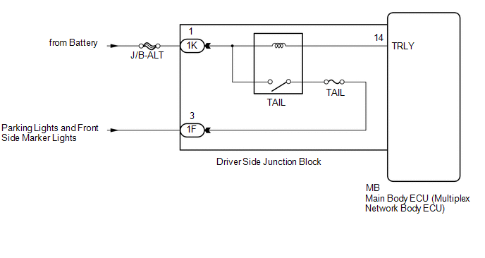
The main body ECU (multiplex network body ECU) controls the operation of the TAIL relay.
WIRING DIAGRAM
CAUTION / NOTICE / HINT
NOTICE:
- Inspect the fuses for circuits related to this system before performing the following inspection procedure.
- If the main body ECU (multiplex network body ECU) is replaced, refer
to Registration (See page
.gif) ).*1
).*1
- *1: w/ Smart Key System
PROCEDURE
|
1. |
PERFORM ACTIVE TEST USING TECHSTREAM (TAILLIGHT RELAY) |
(a) Connect the Techstream to the DLC3.
(b) Turn the ignition switch to ON.
(c) Turn the Techstream on.
(d) Enter the following menus: Body Electrical / Main Body / Active Test.
(e) Perform the Active Test according to the display on the Techstream.
Main Body|
Tester Display |
Test Part |
Control Range |
Diagnostic Note |
|---|---|---|---|
|
Taillight Relay |
Taillight relay |
ON/OFF |
- |
OK:
Taillight relay operates. (Taillights illuminate.)
| OK | .gif) |
PROCEED TO NEXT SUSPECTED AREA SHOWN IN PROBLEM SYMPTOMS TABLE |
|
.gif)
|
2. |
CHECK HARNESS AND CONNECTOR (BATTERY - DRIVER SIDE JUNCTION BLOCK) |
(a) Disconnect the 1K driver side junction block connector.
(b) Measure the voltage according to the value(s) in the table below.
Standard Voltage:
|
Tester Connection |
Condition |
Specified Condition |
|---|---|---|
|
1K-1 - Body ground |
Always |
11 to 14 V |
| NG | |
REPAIR OR REPLACE HARNESS OR CONNECTOR |
|
|
3. |
INSPECT DRIVER SIDE JUNCTION BLOCK |
(a) Remove the driver side junction block (See page
).
(b) Remove the main body ECU (multiplex network body ECU) from the driver side junction block.
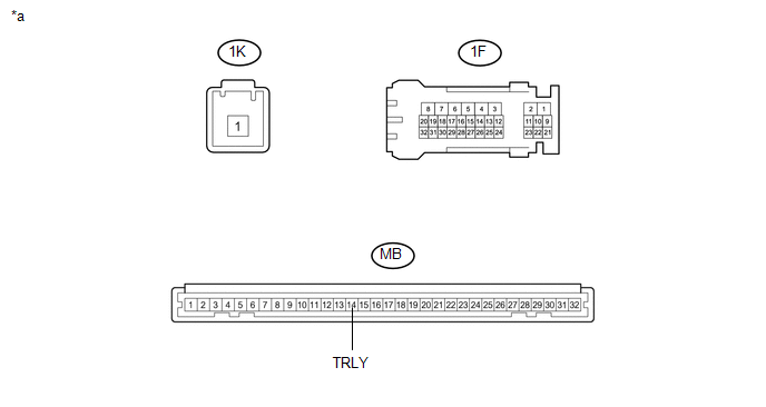 Text in Illustration
|
*a |
Component without harness connected (Driver Side Junction Block) |
- |
- |
(c) Connect a positive (+) lead from the battery to terminal 1K-1.
(d) Connect a negative (-) lead from the battery to terminal MB-14 (TRLY).
(e) Measure the voltage according to the value(s) in the table below.
Standard Voltage:
|
Tester Connection |
Condition |
Specified Condition |
|---|---|---|
|
1F-3 - Battery negative terminal |
Always |
11 to 14 V |
| OK | |
REPLACE MAIN BODY ECU (MULTIPLEX NETWORK BODY ECU) |
| NG | |
REPLACE DRIVER SIDE JUNCTION BLOCK |
 Engine Switch Illumination Circuit
DESCRIPTION
The illuminated entry system controls the engine switch illumination.
WIRING DIAGRAM
PROCEDURE
1.
READ VALUE USING TECHSTREAM (POWER/ENGINE SW LIGHT)
...
 Cargo Light Circuit
DESCRIPTION
The main body ECU (multiplex network body ECU) receives a cargo light information
signal from the deck light switch assembly and door courtesy light switch, and illuminates
the cargo ...
Other materials:
Problem Symptoms Table
PROBLEM SYMPTOMS TABLE
HINT:
Use the table below to help determine the cause of problem symptoms.
If multiple suspected areas are listed, the potential causes of the symptoms
are listed in order of probability in the "Suspected Area" column of the
table. Check each sy ...
Installation
INSTALLATION
PROCEDURE
1. INSTALL TRANSMISSION FLOOR SHIFT ASSEMBLY
(a) Install the transmission floor shift assembly to the vehicle body with the
4 bolts.
Torque:
14 N·m {143 kgf·cm, 10 ft·lbf}
(b) Attach the 4 clamps to connect the wire harness to the transmission floor
shift assembl ...
Cruise Control System Internal Failure (P057504,P057549)
DESCRIPTION
This DTC is stored when there is a malfunction in the ECM.
DTC No.
Detection Item
DTC Detection Condition
Trouble Area
MIL
P057504
Cruise Control System Internal Failure
While the dynamic rada ...
