Toyota Tacoma (2015-2018) Service Manual: System Description
SYSTEM DESCRIPTION
1. FRONT PASSENGER OCCUPANT CLASSIFICATION SYSTEM
(a) General Description
(1) The front passenger occupant detection ECU determines whether the front passenger seat is occupied by an adult or child (with child seat) or is unoccupied, based on the load that is applied to the front passenger seat and whether the seat belt is buckled. The system restricts the deployment of the front passenger airbag, front passenger side airbag, and the front passenger seat belt pretensioner in accordance with this judgment. The result is informed to the driver through the airbag ON/OFF indicator illumination.
(b) System Configuration
(1) This system consists of the occupant detection ECU, occupant classification sensors, airbag ON/OFF indicator, seat belt buckle switches, and airbag sensor assembly.
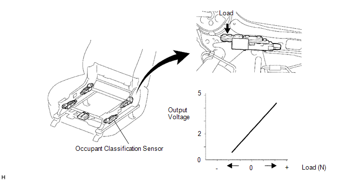
(c) Occupant Detection ECU and Sensor
(1) The occupant classification sensors are installed on four brackets connecting the seat rail and the seat frame. The resistance values of these sensors, which vary in accordance with the load that acts on the brackets, are transmitted to the occupant detection ECU as signals. Upon receipt of the signals, the ECU determines the front passenger seat occupant conditions.
 Initialization
INITIALIZATION
1. ZERO POINT CALIBRATION
NOTICE:
Make sure that the front passenger seat is not occupied before performing the
operation.
HINT:
Perform the zero point calibration and sensitivit ...
 System Diagram
SYSTEM DIAGRAM
...
Other materials:
Data List / Active Test
DATA LIST / ACTIVE TEST
1. DATA LIST
HINT:
Using the Techstream to read the Data List allows the values or states of switches,
sensors, actuators and other items to be read without removing any parts. This non-intrusive
inspection can be very useful because intermittent conditions or signals ...
Rear Differential Lock Position SW Stuck OFF (P17BB)
DESCRIPTION
This DTC is output when an OFF malfunction of the differential lock indicator
switch is detected.
DTC No.
Detection Item
DTC Detection Condition
Trouble Area
P17BB
Rear Differential Lock Position SW Stuck OFF
...
Precaution
PRECAUTION
1. IGNITION SWITCH EXPRESSION
(a) The type of ignition switch used on this model differs depending on the specifications
of the vehicle.
The expressions listed in the table below are used in this section.
Expression
Ignition Switch (Position)
Engine ...
