Toyota Tacoma (2015-2018) Service Manual: Installation
INSTALLATION
PROCEDURE
1. INSTALL VACUUM WARNING SWITCH ASSEMBLY (for 2GR-FKS)
Click here .gif)
2. INSTALL BRAKE VACUUM CHECK VALVE ASSEMBLY (for 2TR-FE)
|
(a) Install a new grommet onto the brake booster assembly. |
|
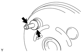
(b) Install the vacuum check valve onto the brake booster assembly.
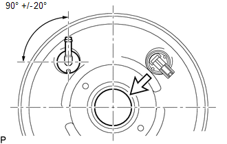
3. INSTALL BRAKE VACUUM CHECK VALVE ASSEMBLY (for 2GR-FKS)
(a) Install a new grommet onto the brake booster assembly.
 Text in Illustration
 |
Center of the Brake Booster Assembly |
(b) Install brake vacuum check valve assembly to the brake booster assembly as shown in the illustration.
4. INSTALL BRAKE BOOSTER ASSEMBLY
(a) Install the push rod clevis.
(b) Install a new gasket onto the brake booster assembly.
(c) Install the brake booster assembly with the 4 nuts.
Torque:
14 N·m {145 kgf·cm, 10 ft·lbf}
(d) Connect the vacuum hose to the brake booster assembly.
(e) Connect the vacuum warning switch assembly connector. (for 2GR-FKS)
5. INSTALL MASTER CYLINDER PUSH ROD CLEVIS
Click here
6. INSTALL BRAKE MASTER CYLINDER SUB-ASSEMBLY
Click here
7. INSTALL LOWER NO. 1 INSTRUMENT PANEL AIRBAG ASSEMBLY
Click here
8. CONNECT CABLE FROM NEGATIVE BATTERY TERMINAL
NOTICE:
When disconnecting the cable, some systems need to be initialized after the cable is reconnected.
Click here
 Inspection
INSPECTION
PROCEDURE
1. INSPECT BRAKE VACUUM CHECK VALVE ASSEMBLY
(a) Check that there is ventilation from the booster to the engine, and
no ventilation from the engine to the booste ...
 Brake Fluid(for Hydraulic Brake Booster)
On-vehicle Inspection
ON-VEHICLE INSPECTION
PROCEDURE
1. INSPECT FLUID LEVEL IN RESERVOIR
(a) Turn the ignition switch to OFF, and depress the brake pedal more
than 40 times (unti ...
Other materials:
Terminals Of Ecu
TERMINALS OF ECU
1. AIRBAG SENSOR ASSEMBLY
Terminal No.
Terminal Symbol
Destination
A21-1
P2+
Instrument panel passenger without door airbag assembly (Front passenger
side squib 2nd step)
A21-2
...
Door Control Receiver
Components
COMPONENTS
ILLUSTRATION
Removal
REMOVAL
PROCEDURE
1. REMOVE ROOF HEADLINING ASSEMBLY (for Double Cab)
(See page )
2. REMOVE ROOF HEADLINING ASSEMBLY (for Access Cab)
(See page )
3. REMOVE DOOR CONTROL RECEIVER (w/o Tire Pressure Warning System)
(a) Disconne ...
Certification Ecu
Components
COMPONENTS
ILLUSTRATION
Installation
INSTALLATION
PROCEDURE
1. INSTALL CERTIFICATION ECU (SMART KEY ECU ASSEMBLY)
(a) Install the certification ECU (smart key ECU assembly) with the 2 nuts.
Torque:
6.5 N·m {66 kgf·cm, 58 in·lbf}
(b) Engage the clamp to install the wire ...
