Toyota Tacoma (2015-2018) Service Manual: Stereo Component Amplifier Disconnected (B15D3)
DESCRIPTION
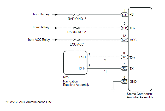
The navigation receiver assembly and stereo component amplifier assembly are connected by the AVC-LAN communication line.
When an AVC-LAN communication error occurs between the navigation receiver assembly and stereo component amplifier assembly, this DTC will be stored.
|
DTC No. |
DTC Detection Condition |
Trouble Area |
|---|---|---|
|
B15D3*1 |
When either condition below is met:
|
|
HINT:
- *1: Even if no fault is present, this DTC may be stored depending on the battery condition or engine start voltage.
- The navigation receiver assembly is the master unit.
WIRING DIAGRAM
CAUTION / NOTICE / HINT
NOTICE:
Inspect the fuses for circuits related to this system before performing the following inspection procedure.
PROCEDURE
|
1. |
CHECK DTC |
(a) If DTC B15C3 is output, perform the troubleshooting of DTC B15C3 first.
Result|
Result |
Proceed to |
|---|---|
|
DTC B15C3 is not output |
A |
|
DTC B15C3 is output |
B |
| B | .gif) |
GO TO DTC "B15C3" IN DIAGNOSTIC TROUBLE CODE CHART |
|
.gif)
|
2. |
CHECK OPTIONAL COMPONENTS (INCLUDING ASSOCIATED WIRING) |
(a) Check that optional components (including associated wiring) which generate radio waves are not installed.
Result|
Result |
Proceed to |
|---|---|
|
Optional components (including associated wiring) are installed. |
A |
|
Optional components (including associated wiring) are not installed. |
B |
HINT:
- Electrical noise from radio waves generated by optional components or the wiring for those components may affect AVC-LAN communication.
- This DTC may be stored when an AVC-LAN communication error occurs due to electrical noise.
| B | |
GO TO STEP 4 |
|
|
3. |
REMOVE OPTIONAL COMPONENTS (INCLUDING ASSOCIATED WIRING) |
(a) Remove optional components (including associated wiring).
NOTICE:
Do not remove optional components or associated wiring without the permission of the customer.
|
|
4. |
CHECK DTC |
(a) Clear the DTCs (See page .gif) ).
).
(b) Recheck for DTCs and check if the same DTC is output again.
OK:
No DTCs are output.
| OK | |
END |
|
|
5. |
CHECK HARNESS AND CONNECTOR (STEREO COMPONENT AMPLIFIER ASSEMBLY POWER SOURCE) |
|
(a) Disconnect the stereo component amplifier assembly connectors. |
|
(b) Measure the resistance according to the value(s) in the table below.
Standard Resistance:
|
Tester Connection |
Condition |
Specified Condition |
|---|---|---|
|
S24-6 (GND) - Body ground |
Always |
Below 1 Ω |
(c) Measure the voltage according to the value(s) in the table below.
Standard Voltage:
|
Tester Connection |
Switch Condition |
Specified Condition |
|---|---|---|
|
S31-1 (+B) - S24-6 (GND) |
Always |
11 to 14 V |
|
S31-5 (+B2) - S24-6 (GND) |
Always |
11 to 14 V |
|
S23-12 (ACC) - S24-6 (GND) |
Ignition switch ACC |
11 to 14 V |
|
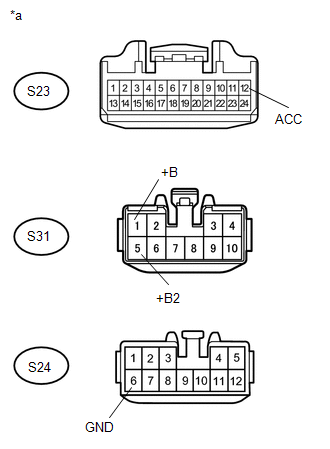
*a |
Front view of wire harness connector (to Stereo Component Amplifier Assembly) |
| NG | |
REPAIR OR REPLACE HARNESS OR CONNECTOR |
|
|
6. |
CHECK HARNESS AND CONNECTOR (NAVIGATION RECEIVER ASSEMBLY - STEREO COMPONENT AMPLIFIER ASSEMBLY) |
(a) Disconnect the N25 navigation receiver assembly connector.
(b) Disconnect the S23 stereo component amplifier assembly connector.
(c) Measure the resistance according to the value(s) in the table below.
Standard Resistance:
|
Tester Connection |
Condition |
Specified Condition |
|---|---|---|
|
N25-7 (TX1+) - S23-8 (TX+) |
Always |
Below 1 Ω |
|
N25-8 (TX1-) - S23-7 (TX-) |
Always |
Below 1 Ω |
|
N25-7 (TX1+) - Body ground |
Always |
10 kΩ or higher |
|
N25-8 (TX1-) - Body ground |
Always |
10 kΩ or higher |
| NG | |
REPAIR OR REPLACE HARNESS OR CONNECTOR |
|
|
7. |
REPLACE STEREO COMPONENT AMPLIFIER ASSEMBLY |
(a) Replace the stereo component amplifier assembly (See page
).
(b) Clear the DTCs (See page ).
(c) Recheck for DTCs and check if the same DTC is output again.
OK:
No DTCs are output.
| OK | |
END |
| NG | |
REPLACE NAVIGATION RECEIVER ASSEMBLY |
 Sending Malfunction (Navigation to APGS) (U0073,U0100,U0129,U0140,U0155,U0164)
DESCRIPTION
These DTCs are stored when a malfunction occurs in the CAN communication circuit.
DTC Code
DTC Detection Condition
Trouble Area
U0073
...
 Voice Recognition Microphone Disconnected (B1579)
DESCRIPTION
The navigation receiver assembly and telephone microphone assembly are connected
to each other using the microphone connection detection signal lines.
This DTC is stored when the micro ...
Other materials:
Input Speed Sensor Circuit No Signal (P0717,P07BF,P07C0)
DESCRIPTION
This sensor detects the rotation speed of the turbine which shows the input turbine
speed of the transmission. By comparing the input turbine speed signal (NT) with
the output shaft speed sensor signal (SP2), the ECM detects the shift timing of
the gears and appropriately controls ...
While Alarm is Armed, Battery is Reconnected but Alarm does not Sound
DESCRIPTION
While the alarm is armed, the EEPROM inside the main body ECU (multiplex network
body ECU) will remember the armed state even if the battery is disconnected, and
the alarm will sound when the battery is reconnected.
If the alarm does not sound when the battery is reconnected, the a ...
Disposal
DISPOSAL
CAUTION / NOTICE / HINT
CAUTION:
Before performing pre-disposal deployment of any SRS component, review and closely
follow all applicable environmental and hazardous material regulations. Pre-disposal
deployment may be considered hazardous material treatment.
PROCEDURE
1. PRECAUTIO ...
