Toyota Tacoma (2015-2018) Service Manual: Slip Indicator Light Remains ON
DESCRIPTION
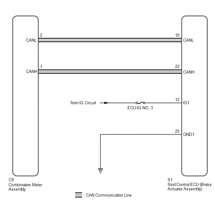
The skid control ECU (brake actuator assembly) is connected to the combination meter assembly via CAN communication.
The slip indicator light blinks during VSC and/or TRAC operation.
If a malfunction is detected, the slip indicator light comes on to warn the driver
(See page .gif) ).
).
w/ Rear Differential Lock:
When the rear differential cannot be unlocked for 2 consecutive trips, the slip indicator light illuminates.
WIRING DIAGRAM
CAUTION / NOTICE / HINT
NOTICE:
- When replacing the skid control ECU (brake actuator assembly), perform
zero point calibration and store system information (See page
).
- Inspect the fuses for circuits related to this system before performing the following inspection procedure.
- w/ Rear Differential Lock:
As there may be malfunctions in the differential system related to when the system operates with the rear differential locked, check the differential system first (See page
).
PROCEDURE
|
1. |
CHECK CAN COMMUNICATION SYSTEM |
(a) Check if CAN communication system DTCs are output (See page
).
|
Result |
Proceed to |
|---|---|
|
DTC is not output |
A |
|
DTC is output |
B |
| B | .gif) |
CHECK CAN COMMUNICATION SYSTEM |
|
.gif)
|
2. |
CHECK IF SKID CONTROL ECU CONNECTOR IS SECURELY CONNECTED |
(a) Check if the skid control ECU (brake actuator assembly) connector is securely connected.
OK:
The connector is securely connected.
| NG | |
CONNECT CONNECTOR TO ECU CORRECTLY |
|
|
3. |
INSPECT BATTERY |
(a) Check the battery voltage.
Standard voltage:
11 to 14 V
| NG | |
CHECK OR REPLACE CHARGING SYSTEM OR BATTERY |
|
|
4. |
CHECK TERMINAL VOLTAGE (IG1 TERMINAL) |
|
(a) Disconnect the S1 skid control ECU (brake actuator assembly) connector. |
|
.png)
(b) Turn the ignition switch to ON.
(c) Measure the voltage according to the value(s) in the table below.
Standard Voltage:
|
Tester Connection |
Switch Condition |
Specified Condition |
|---|---|---|
|
S1-12 (IG1) - Body ground |
Ignition switch ON |
11 to 14 V |
|
*A |
Front view of wire harness connector (to Skid Control ECU [Brake Actuator Assembly]) |
| NG | |
REPAIR OR REPLACE HARNESS OR CONNECTOR (IG1 CIRCUIT) |
|
|
5. |
CHECK HARNESS AND CONNECTOR (GND1 TERMINAL) |
(a) Turn the ignition switch off.
|
(b) Measure the resistance according to the value(s) in the table below. Standard Resistance:
|
|
.png)
| NG | |
REPAIR OR REPLACE HARNESS OR CONNECTOR (GND1 CIRCUIT) |
|
|
6. |
READ VALUE USING TECHSTREAM (SLIP INDICATOR LIGHT) |
(a) Reconnect the S1 skid control ECU (brake actuator assembly) connector.
(b) Connect the Techstream to the DLC3.
(c) Turn the ignition switch to ON.
(d) Turn the Techstream on.
(e) Enter the following menus: Chassis / ABS/VSC/TRAC / Data List.
(f) According to the display on the Techstream, read the Data List.
ABS/VSC/TRAC|
Tester Display |
Measurement Item |
Range |
Normal Condition |
Diagnostic Note |
|---|---|---|---|---|
|
Slip Indicator Light |
SLIP indicator light |
OFF or ON |
OFF: Indicator light off ON: Indicator light on |
- |
(g) Check the Techstream display condition of the slip indicator light.
Result|
Result |
Proceed to |
|---|---|
|
Display of the Data List remains OFF |
A |
|
Display of the Data List remains ON |
B |
| A | |
INSPECT METER / GAUGE SYSTEM |
| B | |
REPLACE BRAKE ACTUATOR ASSEMBLY |
 Brake Warning Light does not Come ON
DESCRIPTION
The skid control ECU (brake actuator assembly) is connected to the combination
meter assembly via CAN communication.
WIRING DIAGRAM
Refer to Brake Warning Light Remains ON (See page
...
 AUTO LSD Indicator Light does not Come ON
DESCRIPTION
The AUTO LSD does not operate even if the VSC OFF switch is pressed under the
following conditions:
The brake system is faulty.
The temperature inside the hydraulic brake bo ...
Other materials:
On-vehicle Inspection
ON-VEHICLE INSPECTION
PROCEDURE
1. INSPECT GARAGE DOOR OPENER
(a) Press each switch and check that the red LED turns on. If one or
more of the switches does not turn on the LED, confirm normal operation
of the fuse and wire harness. If the fuse and wire harness are malfunctioni ...
Rear seats (Access Cab and Double Cab models)
Access Cab models
The bottom cushion of the rear seats can be raised and lowered.
■ Before raising the bottom cushion
Stow the seat belt buckles.
This prevents the seat belt buckles from falling out when you fold the seatback.
■ Raising the bottom cushion
Raise the bottom cushi ...
Lost Communication with ECM / PCM "A" (U0100-U0142,U0155)
DESCRIPTION
These DTCs are stored when the clearance warning ECU assembly cannot receive
and recognize several signals via the CAN communication system.
DTC No.
DTC Detection Condition
Trouble Area
U0100
Lost Communication with ECM / P ...
