Toyota Tacoma (2015-2018) Service Manual: AUTO LSD Indicator Light does not Come ON
DESCRIPTION
The AUTO LSD does not operate even if the VSC OFF switch is pressed under the following conditions:
- The brake system is faulty.
- The temperature inside the hydraulic brake booster increases and the AUTO LSD operation is suspended.
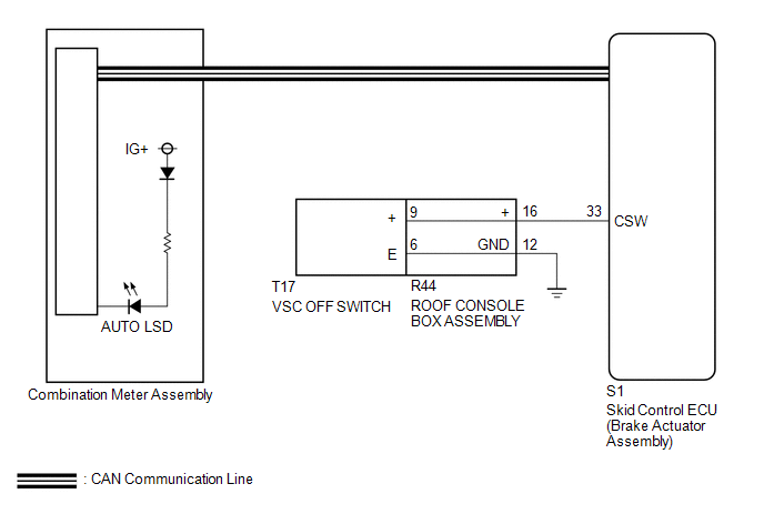
WIRING DIAGRAM
CAUTION / NOTICE / HINT
NOTICE:
When replacing the brake actuator assembly, perform calibration (See page
.gif) ).
).
PROCEDURE
|
1. |
CHECK CAN COMMUNICATION LINE |
(a) Turn the ignition switch off.
(b) Connect the Techstream to the DLC3.
(c) Turn the ignition switch to ON.
(d) Turn the Techstream on.
(e) Select CAN Bus Check from the System Selection Menu screen and follow the
prompts on the screen to inspect the CAN bus (See page
).
OK:
CAN Bus Check indicates no malfunctions in CAN communication.
| NG | .gif) |
GO TO CAN COMMUNICATION SYSTEM (HOW TO PROCEED WITH TROUBLESHOOTING) |
|
.gif)
|
2. |
INSPECT VSC OFF SWITCH |
(a) Turn the ignition switch off.
(b) Remove the VSC OFF switch (See page ).
(c) Inspect the VSC OFF switch (See page ).
OK:
The VSC OFF switch operates normally.
| NG | |
REPLACE VSC OFF SWITCH |
|
|
3. |
CHECK HARNESS AND CONNECTOR (BRAKE ACTUATOR ASSEMBLY - VSC OFF SWITCH) |
(a) Disconnect the S1 skid control ECU (brake actuator assembly) connector.
(b) Measure the resistance according to the value(s) in the table below.
Standard Resistance:
|
Tester Connection |
Condition |
Specified Condition |
|---|---|---|
|
S1-33 (CSW) - R44-16 |
Always |
Below 1 Ω |
|
S1-33 (CSW) or R44-16 -Body ground |
Always |
10 kΩ or higher |
|
R44-12 - Body ground |
Always |
Below 1 Ω |
| NG | |
REPAIR OR REPLACE HARNESS OR CONNECTOR |
|
|
4. |
READ VALUE USING TECHSTREAM (AUTO LSD INDICATOR LIGHT) |
(a) Turn the ignition switch off.
(b) Connect the Techstream to the DLC3.
(c) Turn the ignition switch to ON.
(d) Turn the Techstream on.
(e) Enter the following menus: Chassis / ABS/VSC/TRAC / Data List.
ABS/VSC/TRAC|
Tester Display |
Measurement Item/Range |
Normal Condition |
Diagnostic Note |
|---|---|---|---|
|
Auto LSD Indicator Light |
Auto LSD indicator light/ ON or OFF |
ON: Indicator light on OFF: Indicator light off |
- |
(f) When performing the Auto LSD Indicator Light Active Test, check Auto LSD
Indicator Light in the Data List (See page
).
|
Tester Display |
Test Part |
Control Range |
Diagnostic Note |
|---|---|---|---|
|
Auto LSD Indicator Light |
Auto LSD indicator light |
Indicator light ON/OFF |
Observe the combination meter. |
|
Result |
Proceed to |
|
|---|---|---|
|
Data List Display |
Data List Display when Performing Active Test ON/OFF Operation |
|
|
ON |
Does not change between ON and OFF |
A |
|
Changes between ON and OFF |
B |
|
|
OFF |
Does not change between ON and OFF |
A |
|
Changes between ON and OFF |
B |
|
| A | |
REPLACE MASTER CYLINDER SOLENOID |
| B | |
GO TO METER / GAUGE SYSTEM (HOW TO PROCEED WITH TROUBLESHOOTING) |
 Slip Indicator Light Remains ON
DESCRIPTION
The skid control ECU (brake actuator assembly) is connected to the combination
meter assembly via CAN communication.
The slip indicator light blinks during VSC and/or TRAC operation.
...
 AUTO LSD Indicator Light Remains ON
DESCRIPTION
During normal mode, pressing the VSC OFF switch for a short amount of time changes
vehicle to AUTO LSD mode.
WIRING DIAGRAM
CAUTION / NOTICE / HINT
NOTICE:
When replacing the brak ...
Other materials:
Air Fuel Ratio Sensor
Components
COMPONENTS
ILLUSTRATION
Removal
REMOVAL
PROCEDURE
1. REMOVE AIR FUEL RATIO SENSOR (for Bank 1 Sensor 1)
(a) Disconnect the air fuel ratio sensor connector.
(b) Disengage the clamp to separate the air fuel ratio sensor wire ...
Road Test
ROAD TEST
HINT:
'SET' and '-', 'RES' and '+', 'ON-OFF' functions share the same switch. Operate
the cruise control main switch according to the directions indicated on the switch.
1. INSPECT 'SET' FUNCTION
(a) Push the ON-OFF button on (A).
(b ...
On-vehicle Inspection
ON-VEHICLE INSPECTION
PROCEDURE
1. INSPECT PARK/NEUTRAL POSITION SWITCH
(a) Apply the parking brake.
(b) Turn the ignition switch to ON.
(c) Depress the brake pedal and move the shift lever to any position other than
P.
(d) Depress the brake pedal and check that the engine starts when the sh ...
