Toyota Tacoma (2015-2018) Service Manual: Short in GPS Antenna (B15C0,B15C1)
DESCRIPTION
These DTCs are stored when a malfunction occurs in the navigation antenna assembly.
|
DTC No. |
DTC Detection Condition |
Trouble Area |
|---|---|---|
|
B15C0 |
Navigation antenna error |
|
|
B15C1 |
Error of the power source to the navigation antenna |
CAUTION / NOTICE / HINT
NOTICE:
Check that the navigation antenna assembly cable is properly installed and does
not have any sharp bends, pinching or loose connections before performing following
inspection procedure (See page .gif) ).
).
PROCEDURE
|
1. |
CHECK DTC |
(a) Clear the DTCs (See page ).
(b) Recheck for DTCs and check that no DTCs are output.
OK:
No DTCs are output.
| OK | .gif) |
USE SIMULATION METHOD TO CHECK |
|
.gif)
|
2. |
INSPECT NAVIGATION ANTENNA ASSEMBLY |
|
(a) Remove the navigation antenna assembly (See page
|
|
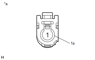
(b) Measure the resistance according to the value(s) in the table below.
Standard Resistance:
|
Tester Connection |
Condition |
Specified Condition |
|---|---|---|
|
1 - 1a |
Always |
50 to 500 Ω |
|
*a |
Component without harness connected (Navigation Antenna Assembly) |
| OK | |
REPLACE NAVIGATION RECEIVER ASSEMBLY |
| NG | |
REPLACE NAVIGATION ANTENNA ASSEMBLY |
 Stereo Component Amplifier Malfunction (B15A3)
DESCRIPTION
This DTC is stored when a malfunction occurs in the stereo component amplifier
assembly.
DTC No.
DTC Detection Condition
Trouble Area
...
 Speed Signal Malfunction (B15C2)
DESCRIPTION
The navigation receiver assembly receives a vehicle speed signal from the combination
meter assembly and information from the navigation antenna assembly, and then adjusts
the vehicle ...
Other materials:
Cautions & Notices
CAUTION
This is a warning against anything which may cause injury to people if the
warning is ignored. You are informed about what you must or must not do in order
to reduce the risk of injury to yourself and others.
NOTICE
This is a warning against anything which may cause damage to the vehi ...
Mechanical System Tests
MECHANICAL SYSTEM TESTS
1. STALL SPEED TEST
HINT:
This test is to check the overall performance of the engine and transmission.
CAUTION:
This test should be done on a paved surface (a surface that is not slippery).
To ensure safety, perform this test in an open and level area tha ...
Brake System Malfunction (C1A50)
DESCRIPTION
When the pre-collision system is operating, the millimeter wave radar sensor
assembly sends brake control signals to the skid control ECU (master cylinder solenoid)*1
or skid control ECU (brake actuator assembly)*2.
If the millimeter wave radar sensor assembly receives a vehicle st ...
