Toyota Tacoma (2015-2018) Service Manual: Installation
INSTALLATION
CAUTION / NOTICE / HINT
HINT:
- Use the same procedure for both the RH and LH sides.
- The procedure described below is for the LH side.
PROCEDURE
1. INSTALL FRONT SHOULDER BELT ANCHOR ADJUSTER ASSEMBLY
|
(a) Engage the guide to temporarily install the front shoulder belt anchor adjuster assembly with the 2 bolts. |
|
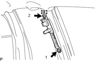
(b) Tighten the 2 bolts in the order shown in the illustration.
Torque:
42 N·m {428 kgf·cm, 31 ft·lbf}
2. INSTALL FRONT SEAT OUTER BELT ASSEMBLY
|
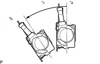
(a) Before installing the front seat outer belt assembly, check the ELR function. Text in Illustration
(1) When the inclination of the retractor is 15° or less, check that the belt can be pulled from the retractor. When the inclination of the retractor is over 45°, check that the belt locks. NOTICE: Do not disassemble the retractor. If operation is not as specified, replace the front seat outer belt assembly. |
|
(b) Engage the 2 guides and install the front seat outer belt assembly with the bolt.
Torque:
12.5 N·m {127 kgf·cm, 9 ft·lbf}
|
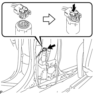
(c) Connect the pretensioner connector and lock the locking button as shown in the illustration. |
|
(d) Connect the shoulder anchor with the nut.
Torque:
42 N·m {428 kgf·cm, 31 ft·lbf}
(e) Check that the shoulder anchor rotates smoothly.
(f) Connect the floor anchor of the front seat outer belt assembly with the bolt.
Torque:
42 N·m {428 kgf·cm, 31 ft·lbf}
(g) Check the ELR lock.
NOTICE:
The check should be performed with the front seat outer belt assembly installed.
(1) With the belt installed, check that the belt locks when it is pulled out quickly.
If the operation is not as specified, replace the front seat outer belt assembly.
(h) Remove the bolt to disconnect the floor anchor.
3. INSTALL CENTER PILLAR UPPER GARNISH
Click here .gif)
4. INSTALL CENTER PILLAR LOWER GARNISH
Click here
5. CONNECT FRONT SEAT OUTER BELT ASSEMBLY
Click here
6. INSTALL LAP BELT OUTER ANCHOR COVER
Click here
7. CONNECT REAR DOOR OPENING TRIM WEATHERSTRIP
(a) Connect the rear door opening trim weatherstrip.
8. CONNECT FRONT DOOR OPENING TRIM WEATHERSTRIP
(a) Connect the front door opening trim weatherstrip.
9. INSTALL REAR DOOR SCUFF PLATE
Click here
10. INSTALL FRONT DOOR SCUFF PLATE
Click here
11. CONNECT CABLE TO NEGATIVE BATTERY TERMINAL
Torque:
5.4 N·m {55 kgf·cm, 48 in·lbf}
NOTICE:
When disconnecting the cable, some systems need to be initialized after the cable is reconnected.
Click here
12. INSPECT SRS WARNING LIGHT
Click here
 Components
COMPONENTS
ILLUSTRATION
...
 Removal
REMOVAL
CAUTION / NOTICE / HINT
HINT:
Use the same procedure for both the RH and LH sides.
The procedure described below is for the LH side.
PROCEDURE
1. PRECAUTION
NOTICE:
Af ...
Other materials:
Installation
INSTALLATION
CAUTION / NOTICE / HINT
HINT:
Use the same procedure for the RH and LH sides.
The procedure described below is for the LH side.
PROCEDURE
1. REPAIR INSTRUCTION
(a) Clean the vehicle body surface.
(1) Using a heat light, heat the vehicle body surface.
Heating Te ...
Terminals Of Ecu
TERMINALS OF ECU
1. CHECK DRIVER SIDE JUNCTION BLOCK AND MAIN BODY ECU (MULTIPLEX NETWORK BODY
ECU)
(a) Disconnect the MB main body ECU (multiplex network body ECU) connectors.
(b) Measure the voltage and resistance according to the value(s) in the table
below.
HINT:
Measure the values on ...
Disposal
DISPOSAL
CAUTION / NOTICE / HINT
CAUTION:
Before performing pre-disposal deployment of any SRS part, review and closely
follow all applicable environmental and hazardous material regulations. Predisposal
deployment may be considered hazardous material treatment.
PROCEDURE
1. PRECAUTION
...
