Toyota Tacoma (2015-2018) Service Manual: Security Horn Assembly
Components
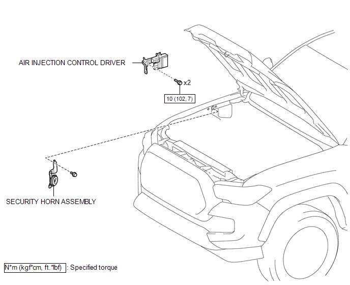
COMPONENTS
ILLUSTRATION
Inspection
INSPECTION
PROCEDURE
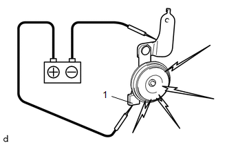
1. INSPECT SECURITY HORN ASSEMBLY
|
(a) Check the operation. (1) Apply battery voltage and check operation of the security horn assembly. OK:
If the result is not as specified, replace the security horn assembly. |
|
Removal
REMOVAL
PROCEDURE
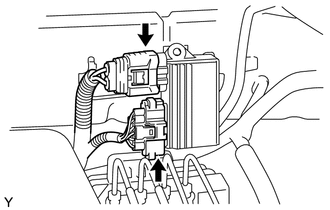
1. REMOVE AIR INJECTION CONTROL DRIVER (for 2TR-FE)
|
(a) Disconnect the 2 connectors. |
|
|
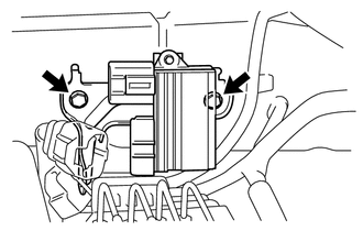
(b) Remove the 2 bolts and air injection control driver. |
|
2. REMOVE SECURITY HORN ASSEMBLY
|
(a) Disconnect the connector. |
|
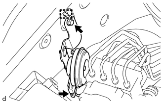
(b) Remove the bolt.
(c) Disengage the guide to remove the security horn assembly.
Installation
INSTALLATION
PROCEDURE
1. INSTALL SECURITY HORN ASSEMBLY
(a) Engage the guide to install the security horn assembly.
(b) Install the bolt.
(c) Connect the connector.
2. INSTALL AIR INJECTION CONTROL DRIVER (for 2TR-FE)
(a) Install the air injection control driver with the 2 bolts.
Torque:
10 N·m {102 kgf·cm, 7 ft·lbf}
(b) Connect the 2 connectors.
 Engine Hood Courtesy Switch
Components
COMPONENTS
ILLUSTRATION
Inspection
INSPECTION
PROCEDURE
1. INSPECT HOOD COURTESY SWITCH (HOOD LOCK ASSEMBLY)
(a) Check the resistance.
(1) Measure the resistance ac ...

Other materials:
Utility
UTILITY
NOTICE:
If the forward recognition camera has been replaced with a new one or
the windshield glass has been removed and installed, it is necessary to
perform Forward Recognition Camera Axis Adjustment. If the system is turned
on without performing Forward Recognition Ca ...
Steering Angle Sensor Internal Circuit (C1433)
DESCRIPTION
The skid control ECU (brake actuator assembly) outputs this DTC when it receives
an internal malfunction signal from the steering angle sensor.
DTC No.
Detection Item
DTC Detection Condition
Trouble Area
C1433
St ...
Inspection
INSPECTION
PROCEDURE
1. INSPECT COOLER (ROOM TEMPERATURE. SENSOR) THERMISTOR
(a) Check the resistance.
(1) Measure the resistance according to the value(s) in the table below.
Text in Illustration
*a
Component without harness connected
(coo ...
