Toyota Tacoma (2015-2018) Service Manual: Components
COMPONENTS
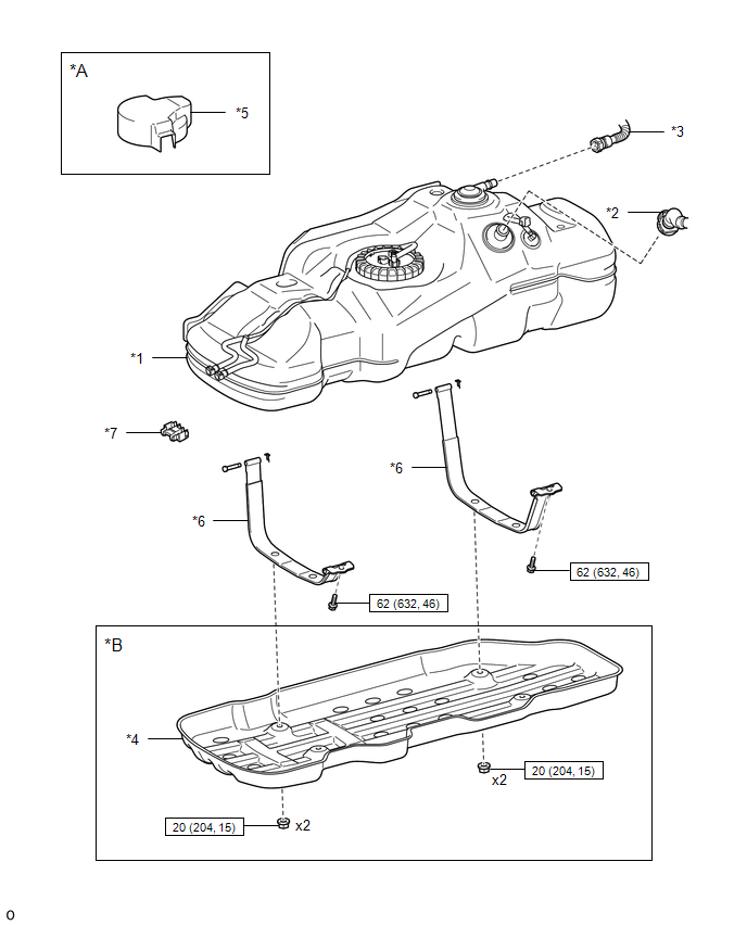
ILLUSTRATION
|
*A |
w/ Fuel Tank Cover |
*B |
for Hydraulic Brake Booster |
|
*1 |
FUEL TANK ASSEMBLY |
*2 |
FUEL TANK INLET PIPE SUB-ASSEMBLY |
|
*3 |
FUEL TANK VENT HOSE SUB-ASSEMBLY |
*4 |
NO. 1 FUEL TANK PROTECTOR SUB-ASSEMBLY |
|
*5 |
FUEL TANK COVER |
*6 |
FUEL TANK BAND |
|
*7 |
FUEL PIPE CLAMP |
- |
- |
.png) |
N*m (kgf*cm, ft.*lbf): Specified torque |
- |
- |
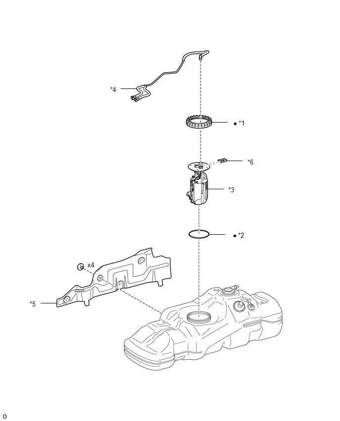
ILLUSTRATION
|
*1 |
FUEL PUMP GAUGE RETAINER |
*2 |
FUEL SUCTION TUBE SET GASKET |
|
*3 |
FUEL SUCTION TUBE WITH PUMP AND GAUGE ASSEMBLY |
*4 |
FUEL TANK MAIN TUBE SUB-ASSEMBLY |
|
*5 |
NO. 1 FUEL TANK PROTECTOR |
*6 |
TUBE JOINT CLIP |
|
â—Ź |
Non-reusable part |
- |
- |
 Fuel Tank
...
 Removal
REMOVAL
PROCEDURE
1. PRECAUTION
NOTICE:
After turning the ignition switch off, waiting time may be required before disconnecting
the cable from the battery terminal. Therefore, make sure to read ...
Other materials:
Precaution
PRECAUTION
1. EXPRESSIONS OF IGNITION SWITCH
(a) The type of ignition switch used on this model differs according to the specifications
of the vehicle. The expressions listed in the table below are used in this section.
Expression
Ignition Switch (Position)
Engi ...
Problem Symptoms Table
PROBLEM SYMPTOMS TABLE
HINT:
Troubleshooting of the theft deterrent system is based on the premise
that the power door lock control system, wireless door lock control system*1
and smart key system*2 are operating normally. Accordingly, before troubleshooting
the theft deterrent ...
Security Horn Assembly
Components
COMPONENTS
ILLUSTRATION
Inspection
INSPECTION
PROCEDURE
1. INSPECT SECURITY HORN ASSEMBLY
(a) Check the operation.
(1) Apply battery voltage and check operation of the security horn assembly.
OK:
Measurement Condition
Spe ...
