Toyota Tacoma (2015-2018) Service Manual: Data Signal Circuit between Radio Receiver and Extension Module
DESCRIPTION
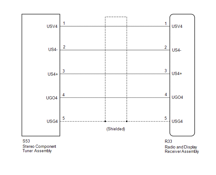
The stereo component tuner assembly sends the image data signal to the radio and display receiver assembly via this circuit.
WIRING DIAGRAM
PROCEDURE
|
1. |
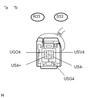
CHECK NO. 1 NAVIGATION WIRE |
(a) Disconnect the R33 radio and display receiver assembly connector.
(b) Disconnect the S53 stereo component tuner assembly connector.
|
(c) Measure the resistance according to the value(s) in the table below. Standard Resistance:
|
|
| OK | .gif) |
PROCEED TO NEXT SUSPECTED AREA SHOWN IN PROBLEM SYMPTOMS TABLE |
| NG | |
REPLACE NO. 1 NAVIGATION WIRE |
 Data Signal Circuit between Radio Receiver and Stereo Jack Adapter
DESCRIPTION
The No. 1 stereo jack adapter assembly sends the sound data signal or image data
signal from a USB device to the radio and display receiver assembly via this circuit.
WIRING DIAGRAM
...
 Microphone Circuit between Microphone and Radio Receiver
DESCRIPTION
The radio and display receiver assembly and telephone microphone assembly are
connected to each other using the microphone connection detection signal lines.
Using this circuit, the ra ...
Other materials:
Problem Symptoms Table
PROBLEM SYMPTOMS TABLE
Charging System
Symptom
Suspected Area
See page
Charging System Warning Displayed
Battery
Generator assembly
Charging system (ON-VEHICLE INSPECTION)
...
Precaution
PRECAUTION
1. IGNITION SWITCH EXPRESSIONS
(a) The type of ignition switch used on this model differs according to the specifications
of the vehicle. The expressions listed in the table below are used in this section.
Expression
Ignition Switch (Position)
Engine ...
Removal
REMOVAL
PROCEDURE
1. PRECAUTION
NOTICE:
After turning the ignition switch off, waiting time may be required before disconnecting
the cable from the negative (-) battery terminal. Therefore, make sure to read the
disconnecting the cable from the negative (-) battery terminal notices before pr ...
