Toyota Tacoma (2015-2018) Service Manual: Removal
REMOVAL
CAUTION / NOTICE / HINT
HINT:
- Use the same procedure for both the RH and LH sides.
- The procedure described below is for the LH side.
PROCEDURE
1. PRECAUTION
CAUTION:
Be sure to read Precaution thoroughly before servicing (See page
.gif) ).
).
NOTICE:
After turning the ignition switch off, waiting time may be required before disconnecting the cable from the negative (-) battery terminal. Therefore, make sure to read the disconnecting the cable from the negative (-) battery terminal notices before proceeding with work.
Click here
2. DISCONNECT CABLE FROM NEGATIVE BATTERY TERMINAL
CAUTION:
Wait at least 90 seconds after disconnecting the cable from the negative (-) battery terminal to disable the SRS system.
NOTICE:
When disconnecting the cable, some systems need to be initialized after the cable is reconnected.
Click here
3. REMOVE ROOF HEADLINING ASSEMBLY
Click here
4. REMOVE CURTAIN SHIELD AIRBAG ASSEMBLY
|
(a) Using a screwdriver with its tip wrapped in protective tape, release the airbag connector lock. Text in Illustration
|
|
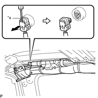
(b) Disconnect the connector.
NOTICE:
When handling the airbag connector, take care not to damage the airbag wire harness.
(c) Using needle nose pliers, remove the 2 pins from the 2 clips.
 Text in Illustration
|
*1 |
Clip |
*2 |
Spacer |
|
*a |
Pin |
- |
- |
HINT:
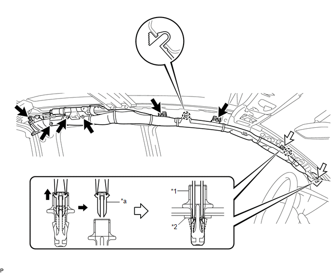
Remove the 2 clips and curtain shield airbag assembly from the vehicle body as a unit.
(d) While holding the curtain shield airbag assembly, remove the 6 bolts, disengage the 2 claws and remove the curtain shield airbag assembly.
(e) Remove the 2 clips and 2 spacers from the curtain shield airbag assembly.
 Installation
INSTALLATION
CAUTION / NOTICE / HINT
HINT:
Use the same procedure for both the RH and LH sides.
The procedure described below is for the LH side.
PROCEDURE
1. INSTALL CURTAIN SH ...

Other materials:
Inspection
INSPECTION
PROCEDURE
1. INSPECT AIR CONDITIONING CONTROL ASSEMBLY
(a) Check the blower switch resistance.
(1) Measure the resistance according to the value(s) in the table below.
Text in Illustration
*a
Component without harness connected
...
Installation
INSTALLATION
PROCEDURE
1. INSTALL PROPELLER SHAFT WITH CENTER BEARING ASSEMBLY
(a) Remove SST from the extension housing.
(b) Install the propeller shaft to the extension housing.
(c) Completely remove any oil or the like and clean the contact surfaces of the
propeller shaft flange and diff ...
Cargo Light Circuit
DESCRIPTION
The main body ECU (multiplex network body ECU) receives a cargo light information
signal from the deck light switch assembly and door courtesy light switch, and illuminates
the cargo light.
WIRING DIAGRAM
CAUTION / NOTICE / HINT
NOTICE:
Inspect the fuses for circuits r ...
