Toyota Tacoma (2015-2018) Service Manual: Removal
REMOVAL
CAUTION / NOTICE / HINT
CAUTION:
- Some of these service operations affect the SRS airbag system. Read
the precautionary notices concerning the SRS airbag system before servicing
(See page
.gif) ).
). - If the side airbag was deployed, replace the front seat assembly with a new one.
PROCEDURE
1. PRECAUTION
NOTICE:
After turning the ignition switch off, waiting time may be required before disconnecting the cable from the negative (-) battery terminal. Therefore, make sure to read the disconnecting the cable from the negative (-) battery terminal notices before proceeding with work.
Click here
2. REMOVE CABLE FROM NEGATIVE BATTERY TERMINAL
CAUTION:
Wait at least 90 seconds after disconnecting the cable from the negative (-) battery terminal to disable the SRS system.
NOTICE:
When disconnecting the cable, some systems need to be initialized after the cable is reconnected.
Click here
3. REMOVE SEAT TRACK COVER
HINT:
Use the same procedures for both sides.
(a) Disengage the 2 claws to remove the seat track cover.
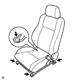
4. REMOVE FRONT SEAT ASSEMBLY
(a) Disengage the wire harness clamp.
(b) Disconnect the connectors.
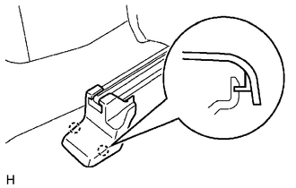
(c) Disconnect the front seat airbag connector.
(1) Place a finger on the slider, slide the slider to release the lock, and then disconnect the front seat airbag connector.
.png) Text in Illustration
Text in Illustration
|
*1 |
Slider |
- |
- |
|
*a |
Push |
*b |
Slide |
(d) Move the seat to the center position.
|
(e) Remove the 4 bolts and front seat assembly. NOTICE: Be careful not to damage the vehicle body. |
|
 Installation
INSTALLATION
CAUTION / NOTICE / HINT
CAUTION:
Some of these service operations affect the SRS airbag system. Read
the precautionary notices concerning the SRS airbag system before servi ...

Other materials:
On-vehicle Inspection
ON-VEHICLE INSPECTION
PROCEDURE
1. INSPECT FLUID LEVEL IN RESERVOIR
(a) Check the fluid level.
If the brake fluid level is lower than the MIN line, check for leaks and inspect
the disc brake pads. If necessary, refill the reservoir with brake fluid to the
MAX line after repair or replaceme ...
Removal
REMOVAL
CAUTION / NOTICE / HINT
Text in Illustration
*a
Object Exceeding Weight Limit of Transmission Jack
Be sure to perform this procedure with several people as the rear differential
carrier assembly is very heavy.
Be sure to follow the procedure ...
Installation
INSTALLATION
CAUTION / NOTICE / HINT
HINT:
Perform "Inspection After Repairs" after replacing the fuel delivery pipe assembly
LH (fuel pressure sensor) (See page ).
PROCEDURE
1. INSTALL FUEL PIPE PLUG SUB-ASSEMBLY
(a) Install a new O-ring, new No. 1 fuel injector back-up ring, new ...
