Toyota Tacoma (2015-2018) Service Manual: Removal
REMOVAL
PROCEDURE
1. REMOVE FRONT DOOR SCUFF PLATE LH (for Double Cab)
.gif)
2. REMOVE FRONT DOOR SCUFF PLATE LH (for Access Cab)
3. REMOVE COWL SIDE TRIM BOARD LH
4. REMOVE CENTER INSTRUMENT CLUSTER CENTER FINISH PANEL SUB-ASSEMBLY
5. REMOVE INSTRUMENT CLUSTER FINISH PANEL ASSEMBLY
6. REMOVE INSTRUMENT PANEL LOWER FINISH PANEL SUB-ASSEMBLY RH
7. REMOVE COOLER (ROOM TEMPERATURE SENSOR) THERMISTOR
(a) Disengage the 2claws to disconnect the cooler (room temperature sensor) thermistor.
|
(b) Disconnect the connector. |
|
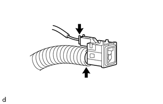
(c) Disconnect the cooler air hose to remove the cooler (room temperature sensor) thermistor.
 Inspection
INSPECTION
PROCEDURE
1. INSPECT COOLER (ROOM TEMPERATURE. SENSOR) THERMISTOR
(a) Check the resistance.
(1) Measure the resistance according to the value(s) in the table below.
Text i ...
 Installation
INSTALLATION
PROCEDURE
1. INSTALL COOLER (ROOM TEMPERATURE SENSOR) THERMISTOR
(a) Connect the cooler air hose.
(b) Connect the connector.
(c) Engage the 2 claws to connect the cooler (room temper ...
Other materials:
Ptc Heater Assembly
Components
COMPONENTS
ILLUSTRATION
Removal
REMOVAL
PROCEDURE
1. REMOVE LOWER NO. 2 INSTRUMENT PANEL AIRBAG ASSEMBLY
(See page )
2. REMOVE INSTRUMENT LOWER PANEL ASSEMBLY
3. REMOVE AIR DUCT ASSEMBLY
4. REMOVE QUICK HEATER ASSEMBLY
(a) Disconnect the connector.
...
High Beam Headlight Circuit
DESCRIPTION
The main body ECU (multiplex network body ECU) controls the high beam headlights.
WIRING DIAGRAM
CAUTION / NOTICE / HINT
NOTICE:
Inspect the fuses for circuits related to this system before performing
the following inspection procedure.
If the main body ECU (multip ...
Dtc Check / Clear
DTC CHECK / CLEAR
NOTICE:
When the diagnosis system is changed from normal mode to check mode or vice versa,
all DTCs and freeze frame data recorded in normal mode are cleared. Before changing
modes, always check and make a note of DTCs and freeze frame data.
HINT:
DTCs which are sto ...
