Toyota Tacoma (2015-2018) Service Manual: Cooling System
On-vehicle Inspection
ON-VEHICLE INSPECTION
PROCEDURE
1. INSPECT FOR COOLANT LEAK
CAUTION:
Do not remove the radiator cap sub-assembly, cylinder block drain cock plug or radiator drain cock plug while the engine and radiator assembly are still hot. Pressurized, hot engine coolant and steam may be released and cause serious burns.
(a) Remove the radiator cap sub-assembly.
(b) Fill the radiator assembly with engine coolant and install a radiator cap tester.
(c) Warm up the engine.
(d) Using the radiator cap tester, increase the pressure inside the radiator assembly to 118 kPa (1.2 kgf/cm2, 17 psi), and then check that the pressure does not drop.
If the pressure drops, check the hose, radiator assembly and engine water pump assembly for leakage. If no external leakage is found, check the heater core, cylinder block sub-assembly and cylinder head sub-assembly.
(e) Remove the radiator cap tester.
(f) Install the radiator cap sub-assembly.
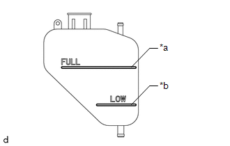
2. INSPECT ENGINE COOLANT LEVEL IN RESERVOIR
|
(a) The engine coolant should be between the LOW and FULL lines when the engine is cold. Text in Illustration
If the engine coolant is below the LOW line, check for leakage and add TOYOTA Super Long Life Coolant (SLLC) or similar high quality ethylene glycol based non-silicate, non-amine, non-nitrite, non-borate coolant with long-life hybrid organic acid technology to the FULL line. NOTICE: Never use water as a substitute for engine coolant. |
|
3. INSPECT ENGINE COOLANT QUALITY
CAUTION:
Do not remove the radiator cap sub-assembly, cylinder block drain cock plug or radiator drain cock plug while the engine and radiator assembly are still hot. Pressurized, hot engine coolant and steam may be released and cause serious burns.
(a) Remove the radiator cap sub-assembly.
(b) Check for excessive deposits of rust or scales around the radiator cap sub-assembly and radiator filler hole. Also, the engine coolant should be free of oil.
If the engine coolant is excessively dirty, replace the engine coolant.
(c) Install the radiator cap sub-assembly.
 Coolant
Replacement
REPLACEMENT
PROCEDURE
1. REMOVE NO. 2 ENGINE UNDER COVER SUB-ASSEMBLY (w/ Off Road Package)
2. REMOVE NO. 1 ENGINE UNDER COVER SUB-ASSEMBLY
3. DRAIN ENGINE COOLANT
CAUTION:
...
 Radiator
...
Other materials:
System Diagram
SYSTEM DIAGRAM
Communication Table
Transmitting ECU (Transmitter)
Receiving ECU (Receiver)
Signal
Line
Main body ECU
(Multiplex Network Body ECU)
Combination Meter Assembly
Wireless door lock hazard warnin ...
Reassembly
REASSEMBLY
CAUTION / NOTICE / HINT
CAUTION:
Wear protective gloves. Sharp areas on the parts may injure your hands.
PROCEDURE
1. INSTALL SEPARATE TYPE REAR SEATBACK COVER
(a) Using hog ring pliers, install the separate type rear seatback cover
with 2 new hog rings.
Text in Il ...
System Diagram
SYSTEM DIAGRAM
1. OVERALL CAN BUS DIAGRAM
(a) The CAN communication system is composed of 4 buses.
CAN Main Bus Line
Terminating Resistor
CAN Branch Line
*
Gateway Function Equipped ECU
...
