Toyota Tacoma (2015-2018) Service Manual: Removal
REMOVAL
PROCEDURE
1. REMOVE PROPELLER SHAFT WITH CENTER BEARING ASSEMBLY
|
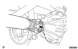
(a) Place matchmarks on the propeller shaft flange yoke and differential flange. Text in Illustration
|
|
(b) for Differential Type BD20:
(1) Remove the 4 nuts, 4 bolts and 4 washers to disconnect the propeller shaft.
(c) for Differential Type BD22:
(1) Remove the 4 nuts and 4 washers to disconnect the propeller shaft.
|
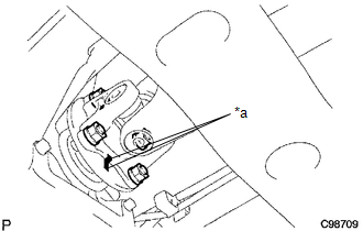
(d) Remove the 2 bolts to separate the center No. 2 support bearing assembly from the frame crossmember. |
|
.png)
|
(e) Place matchmarks on the propeller shaft flange yoke and transfer flange. Text in Illustration
|
|
(f) Remove the 4 nuts, 4 washers and propeller shaft.
 Components
COMPONENTS
ILLUSTRATION
...
 Disassembly
DISASSEMBLY
PROCEDURE
1. REMOVE REAR PROPELLER SHAFT BOOT CLAMP
(a) Place matchmarks on the propeller shaft and sleeve yoke.
Text in Illustration
*1
...
Other materials:
How To Proceed With Troubleshooting
CAUTION / NOTICE / HINT
HINT:
Use these procedure to troubleshoot the seat belt warning system.
*: Use the Techstream.
PROCEDURE
1.
VEHICLE BROUGHT TO WORKSHOP
NEXT
2 ...
Transmission Fluid Temperature Sensor "A" Performance (P0711)
DESCRIPTION
The No. 1 ATF temperature sensor converts the fluid temperature into a resistance
value for use by the ECM.
The ECM applies a voltage to the temperature sensor through terminal THO1 of
the ECM.
The sensor resistance changes with the ATF temperature. As the temperature becomes
hi ...
Removal
REMOVAL
PROCEDURE
1. REMOVE PROPELLER SHAFT WITH CENTER BEARING ASSEMBLY
(a) Place matchmarks on the propeller shaft flange and differential flange.
Text in Illustration
*a
Matchmark
...
