Toyota Tacoma (2015-2018) Service Manual: Components
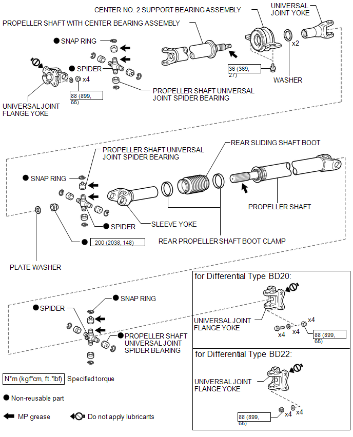
COMPONENTS
ILLUSTRATION

 Removal
REMOVAL
PROCEDURE
1. REMOVE PROPELLER SHAFT WITH CENTER BEARING ASSEMBLY
(a) Place matchmarks on the propeller shaft flange yoke and differential
flange.
Text in Illustration
...
Other materials:
Parts Location
PARTS LOCATION
ILLUSTRATION
*A
for Hydraulic Brake Booster
*B
for Vacuum Brake Booster
*C
w/ Toyota Safety Sense P
-
-
*1
BRAKE BOOSTER ASSEMBLY (SKID CONTROL ECU)
...
IG Supply Voltage Low (C120B)
DESCRIPTION
DTC No.
Detection Item
DTC Detection Condition
Trouble Area
C120B
IG Supply Voltage Low
Master cylinder pressure sensor power supply voltage decrease occurs
or history of voltage decrease exists, and ...
Steering Pad Switch
Components
COMPONENTS
ILLUSTRATION
*1
STEERING PAD SWITCH ASSEMBLY
-
-
Removal
REMOVAL
PROCEDURE
1. REMOVE STEERING PAD
(See page )
2. REMOVE STEERING PAD SWITCH ASSEMBLY
(a) Disconnect the 2 connectors.
...
