Toyota Tacoma (2015-2018) Service Manual: Removal
REMOVAL
PROCEDURE
1. DRAIN DIFFERENTIAL OIL
2. REMOVE PROPELLER WITH CENTER BEARING SHAFT ASSEMBLY (for 2WD)
.gif)
3. REMOVE PROPELLER WITH CENTER BEARING SHAFT ASSEMBLY (for 4WD)
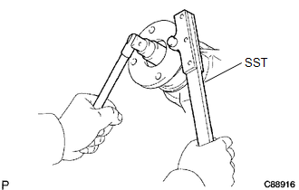
4. REMOVE REAR DRIVE PINION NUT
(a) Using SST and a hammer, unstake the nut.
SST: 09930-00010
(b) for BD20:
|
(1) Using SST to hold the companion flange, remove the nut. SST: 09330-00021 |
|
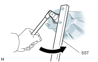
(c) for BD22:
|
(1) Using SST to hold the companion flange, remove the nut. SST: 09330-00021 |
|
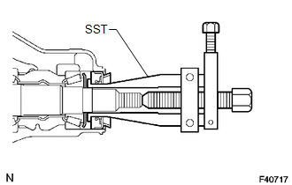
5. REMOVE REAR DRIVE PINION COMPANION FLANGE SUB-ASSEMBLY REAR
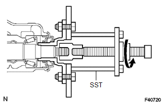
(a) Using SST, remove the companion flange.
SST: 09950-30012
09951-03010
09953-03010
09954-03010
09955-03030
09956-03030
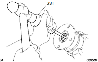
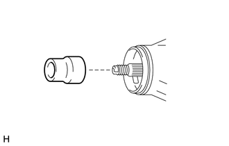
6. REMOVE REAR DIFFERENTIAL CARRIER OIL SEAL
(a) Using SST, remove the oil seal.
SST: 09308-10010
7. REMOVE REAR DIFFERENTIAL DRIVE PINION OIL SLINGER
|
(a) Remove the rear differential drive pinion oil slinger from the differential drive pinion. |
|
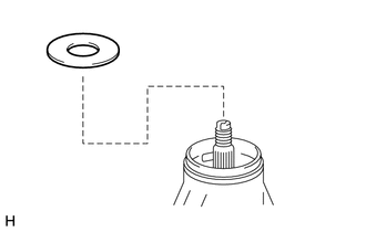
8. REMOVE REAR DRIVE PINION FRONT TAPERED ROLLER BEARING
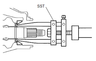
(a) Using SST, remove the front bearing.
SST: 09556-22010
(b) Using SST, remove the front bearing outer race.
SST: 09308-00010
9. REMOVE DIFFERENTIAL OIL STORAGE RING
(a) Using a screwdriver and hammer, tap out the differential oil storage ring.
10. REMOVE REAR DIFFERENTIAL DRIVE PINION BEARING SPACER
|
(a) Remove the front differential drive pinion bearing spacer from the differential drive pinion. |
|

 Installation
INSTALLATION
PROCEDURE
1. INSTALL REAR DIFFERENTIAL DRIVE PINION BEARING SPACER
(a) Install a new front differential drive pinion bearing spacer.
HINT:
Make sure the front differential drive pini ...
Other materials:
Problem Symptoms Table
PROBLEM SYMPTOMS TABLE
HINT:
Use the table below to help determine the cause of problem symptoms. If multiple
suspected areas are listed, the potential causes of the symptoms are listed in order
of probability in the "Suspected Area" column of the table. Check each symptom by
check ...
Reassembly
REASSEMBLY
PROCEDURE
1. INSTALL GENERATOR DRIVE END FRAME BEARING
(a) Using SST and a press, press in a new generator drive end frame bearing.
SST: 09950-60010
09951-00470
SST: 09950-70010
09951-07100
(b) Fit the ta ...
Electrical Key Oscillator(for Rear Floor)
Components
COMPONENTS
ILLUSTRATION
Installation
INSTALLATION
PROCEDURE
1. INSTALL NO. 2 INDOOR ELECTRICAL KEY ANTENNA ASSEMBLY
(a) Engage the clamp to install the No. 2 indoor electrical key antenna assembly.
(b) Connect the connector.
2. INSTALL REAR CONSOLE BOX ASSEMBLY
(See page ...
