Toyota Tacoma (2015-2018) Service Manual: Reassembly
REASSEMBLY
CAUTION / NOTICE / HINT
NOTICE:
Do not try to remove the black nylon tube as it is welded to the fuel suction
tube assembly (See page .gif) ).
).
HINT:
Perform "Inspection After Repairs" after replacing the fuel pump (See page
).
PROCEDURE
1. INSTALL FUEL PUMP
HINT:
Perform "Inspection After Repairs" after replacing the fuel pump (See page
).
|
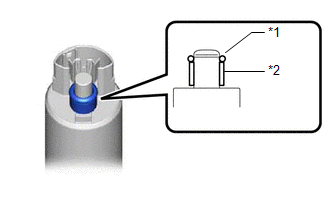
(a) Apply a light coat of gasoline to a new O-ring. Then install the fuel pump spacer and O-ring to the fuel pump. Text in Illustration
|
|
|
(b) Connect the fuel pump harness connector and install the fuel pump harness to the fuel pump. |
|
.png)
|
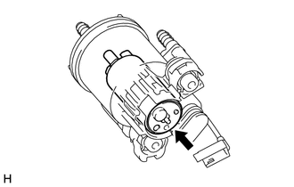
(c) Install the fuel pump to the fuel filter case. NOTICE: Make sure that the O-ring is not cut or pinched during the installation. |
|
|
(d) Engage the 2 claws and install the No. 1 fuel suction support to the fuel filter case. |
|
.png)
|
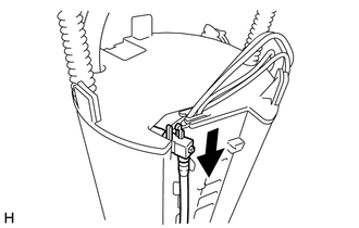
(e) Engage the clamp and connect the wire harness. |
|
.png)
2. INSTALL FUEL PUMP FILTER
|
(a) Engage the claw and connect the fuel pump harness to the fuel pump filter. |
|
.png)
|
(b) Engage the 3 claws and install the fuel pump filter to the fuel filter case. |
|
.png)
3. INSTALL NO. 1 FUEL SUB-TANK
|
(a) Engage the 5 claws and install the No. 1 fuel sub-tank. |
|
.png)
|
(b) While aligning with the installation position of the No. 1 fuel sub-tank, install the jet pump. |
|
(c) Engage the 2 clamps and claw and connect the jet pump nozzle to the No. 1 fuel sub-tank.
|
(d) Engage the clamp and connect the wire harness. |
|
.png)
(e) Connect the 2 fuel pump connectors.
4. INSTALL FUEL SENDER GAUGE ASSEMBLY
 Installation
INSTALLATION
PROCEDURE
1. INSTALL FUEL SUCTION TUBE SET GASKET
(a) Ensure gasket groove is clean and free of foreign particles.
(b) Install a new gasket onto the fuel tank.
...
 Fuel Pump Ecu
Components
COMPONENTS
ILLUSTRATION
Removal
REMOVAL
PROCEDURE
1. PRECAUTION
NOTICE:
After turning the ignition switch off, waiting time may be required before disconnecting
the cable fr ...
Other materials:
Parts Location
PARTS LOCATION
ILLUSTRATION
ILLUSTRATION
ILLUSTRATION
ILLUSTRATION
ILLUSTRATION
...
Fail-safe Chart
FAIL-SAFE CHART
If there is a problem with sensor signals or actuator systems, the skid
control ECU prohibits power supply to the brake actuator assembly and informs
the ECM of a VSC system malfunction.
The brake actuator assembly turns off the solenoids and the ECM stops
its ...
Dtc Check / Clear
DTC CHECK / CLEAR
1. SUPPLEMENTAL RESTRAINT SYSTEM DTC CHECK (USING SST CHECK WIRE)
(a) Check the DTCs (Present DTCs).
(1) Turn the ignition switch to ON, and wait for approximately 60 seconds.
(2) Using SST, connect terminals TC and CG of the DLC3.
SST: 09843-18040
NOTICE:
Connect the term ...
