Toyota Tacoma (2015-2018) Service Manual: Installation
INSTALLATION
PROCEDURE
1. INSTALL LOWER NO. 1 INSTRUMENT PANEL AIRBAG ASSEMBLY
|
(a) Connect the airbag connector. NOTICE: When handling the airbag connector, take care not to damage the airbag wire harness. |
|
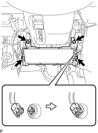
(b) Push in the airbag connector lock to install the airbag connector.
(c) Install the lower No. 1 instrument panel airbag assembly with the 4 bolts.
Torque:
10 N·m {102 kgf·cm, 7 ft·lbf}
2. INSTALL INSTRUMENT PANEL LOWER FINISH PANEL SUB-ASSEMBLY LH
.gif)
3. CONNECT HOOD LOCK CONTROL LEVER SUB-ASSEMBLY
4. INSTALL COWL SIDE TRIM BOARD LH
5. INSTALL FRONT DOOR SCUFF PLATE LH
6. CONNECT CABLE TO NEGATIVE BATTERY TERMINAL
Torque:
5.4 N·m {55 kgf·cm, 48 in·lbf}
NOTICE:
When disconnecting the cable, some systems need to be initialized after the cable is reconnected.
Click here
7. INSPECT SRS WARNING LIGHT
Click here
 Disposal
DISPOSAL
CAUTION / NOTICE / HINT
CAUTION:
Before performing pre-disposal deployment of any SRS part, review and closely
follow all applicable environmental and hazardous material regulations. Pre ...

Other materials:
Main Body ECU Communication Stop Mode
DESCRIPTION
Detection Item
Symptom
Trouble Area
Main Body ECU Communication Stop Mode
Either condition is met:
Communication stop for "Main Body" is indicated on the "Communication
Bus Check" screen ...
Installation
INSTALLATION
PROCEDURE
1. INSTALL PARK/NEUTRAL POSITION SWITCH
HINT:
Make sure that the manual valve lever shaft has not been rotated prior to installing
the park/neutral position switch as the detent spring may become detached from the
manual valve lever shaft.
(a) Clean the bolt and bolt ...
Front Passenger Side Seat Belt Warning Light Malfunction
DESCRIPTION
The occupant classification ECU detects the state of the front seat inner belt
assembly RH and load sensor when the front passenger side seat is occupied with
the ignition switch ON. If the front passenger side seat belt is not fastened, the
front passenger side seat belt warning ...
