Toyota Tacoma (2015-2018) Service Manual: Terminals Of Ecu
TERMINALS OF ECU
1. CHECK MAIN BODY ECU (MULTIPLEX NETWORK BODY ECU)
(a) Disconnect the 1D and 1F driver side junction block connectors.

(b) Measure the voltage and resistance according to the value(s) in the table below.
HINT:
Measure the values on the wire harness side with the connectors disconnected.
|
Tester Connection |
Wiring Color |
Terminal Description |
Condition |
Specified Condition |
|---|---|---|---|---|
|
1F-15 (BECU) - Body ground |
R - Body ground |
Battery power supply |
Always |
11 to 14 V |
|
1D-5 (GND1) - Body ground |
W-B - Body ground |
Ground |
Always |
Below 1 Ω |
If the result is not as specified, there may be a malfunction in the wire harness.
(c) Reconnect the 1D and 1F driver side junction block connectors.
(d) Check for pulses according to the value(s) in the table below.
|
Tester Connection |
Wiring Color |
Terminal Description |
Condition |
Specified Condition |
|---|---|---|---|---|
|
1D-12 (LIN2) - 1D-5 (GND1) |
V - W-B |
LIN communication line |
Ignition switch ON |
Pulse generation |
|
1D-13 (LIN2) - 1D-5 (GND1) |
V - W-B |
LIN communication line |
Ignition switch ON |
Pulse generation |
|
1D-25 (LIN2) - 1D-5 (GND1) |
V - W-B |
LIN communication line |
Ignition switch ON |
Pulse generation |
If the result is not as specified, the main body ECU (multiplex network body ECU) or driver side junction block may be malfunctioning.
2. CHECK FRONT POWER WINDOW REGULATOR MOTOR ASSEMBLY LH (w/ Jam Protection Function)
(a) Disconnect the P24 front power window regulator motor assembly LH connector.

(b) Measure the voltage and resistance according to the value(s) in the table below.
HINT:
Measure the values on the wire harness side with the connector disconnected.
|
Tester Connection |
Wiring Color |
Terminal Description |
Condition |
Specified Condition |
|---|---|---|---|---|
|
P24-2 (B) - P24-1 (GND) |
R - W-B |
Battery power supply |
Always |
11 to 14 V |
|
P24-1 (GND) - Body ground |
W-B - Body ground |
Ground |
Always |
Below 1 Ω |
If the result is not as specified, there may be a malfunction in the wire harness.
(c) Reconnect the P24 front power window regulator motor assembly LH connector.
(d) Check for pulses according to the value(s) in the table below.
|
Tester Connection |
Wiring Color |
Terminal Description |
Condition |
Specified Condition |
|---|---|---|---|---|
|
P24-9 (LIN) - P24-1 (GND) |
GR - W-B |
LIN communication line |
Ignition switch ON |
Pulse generation |
If the result is not as specified, the front power window regulator motor assembly LH may be malfunctioning.
3. CHECK FRONT POWER WINDOW REGULATOR MOTOR ASSEMBLY RH (w/ Jam Protection Function)
(a) Disconnect the P22 front power window regulator motor assembly RH connector.

(b) Measure the voltage and resistance according to the value(s) in the table below.
HINT:
Measure the values on the wire harness side with the connector disconnected.
|
Tester Connection |
Wiring Color |
Terminal Description |
Condition |
Specified Condition |
|---|---|---|---|---|
|
P22-2 (B) - P22-1 (GND) |
W - W-B |
Battery power supply |
Always |
11 to 14 V |
|
P22-1 (GND) - Body ground |
W-B - Body ground |
Ground |
Always |
Below 1 Ω |
If the result is not as specified, there may be a malfunction in the wire harness.
(c) Reconnect the P22 front power window regulator motor assembly RH connector.
(d) Check for pulses according to the value(s) in the table below.
|
Tester Connection |
Wiring Color |
Terminal Description |
Condition |
Specified Condition |
|---|---|---|---|---|
|
P22-9 (LIN) - P22-1 (GND) |
V - W-B |
LIN communication line |
Ignition switch ON |
Pulse generation |
If the result is not as specified, the front power window regulator motor assembly RH may be malfunctioning.
4. CHECK POWER WINDOW REGULATOR MASTER SWITCH ASSEMBLY (for Double Cab with Jam Protection Function)
(a) Disconnect the P18 power window regulator master switch assembly connector.

(b) Measure the voltage and resistance according to the value(s) in the table below.
HINT:
Measure the values on the wire harness side with the connector disconnected.
|
Tester Connection |
Wiring Color |
Terminal Description |
Condition |
Specified Condition |
|---|---|---|---|---|
|
P18-3 (B) - P18-1 (GND) |
R - W-B |
Battery power supply |
Always |
11 to 14 V |
|
P18-1 (GND) - Body ground |
W-B - Body ground |
Ground |
Always |
Below 1 Ω |
If the result is not as specified, there may be a malfunction in the wire harness.
(c) Reconnect the P18 power window regulator master switch assembly connector.
(d) Check for pulses according to the value(s) in the table below.
|
Tester Connection |
Wiring Color |
Terminal Description |
Condition |
Specified Condition |
|---|---|---|---|---|
|
P18-6 (LIN1) - P18-1 (GND) |
V - W-B |
LIN communication line |
Ignition switch ON |
Pulse generation |
|
P18-7 (LIN2) - P18-1 (GND) |
GR - W-B |
LIN communication line |
Ignition switch ON |
Pulse generation |
If the result is not as specified, the power window regulator master switch assembly may be malfunctioning.
5. CHECK POWER WINDOW REGULATOR MASTER SWITCH ASSEMBLY (for Access Cab with Jam Protection Function)
(a) Disconnect the P23 power window regulator master switch assembly connector.

(b) Measure the voltage and resistance according to the value(s) in the table below.
HINT:
Measure the values on the wire harness side with the connector disconnected.
|
Tester Connection |
Wiring Color |
Terminal Description |
Condition |
Specified Condition |
|---|---|---|---|---|
|
P23-11 (B) - P23-12 (GND) |
R - W-B |
Battery power supply |
Always |
11 to 14 V |
|
P23-12 (GND) - Body ground |
W-B - Body ground |
Ground |
Always |
Below 1 Ω |
If the result is not as specified, there may be a malfunction in the wire harness.
(c) Reconnect the P23 power window regulator master switch assembly connector.
(d) Check for pulses according to the value(s) in the table below.
|
Tester Connection |
Wiring Color |
Terminal Description |
Condition |
Specified Condition |
|---|---|---|---|---|
|
P23-17 (LIN1) - P23-12 (GND) |
V - W-B |
LIN communication line |
Ignition switch ON |
Pulse generation |
|
P23-16 (LIN2) - P23-12 (GND) |
GR - W-B |
LIN communication line |
Ignition switch ON |
Pulse generation |
If the result is not as specified, the power window regulator master switch assembly may be malfunctioning.
6. CHECK SLIDING ROOF ECU (SLIDING ROOF DRIVE GEAR SUB-ASSEMBLY) (w/ Sliding Roof)
(a) Disconnect the S50 sliding roof ECU (sliding roof drive gear sub-assembly) connector.

(b) Measure the voltage and resistance according to the value(s) in the table below.
HINT:
Measure the values on the wire harness side with the connector disconnected.
|
Tester Connection |
Wiring Color |
Terminal Description |
Condition |
Specified Condition |
|---|---|---|---|---|
|
S50-8 (B) - S50-12 (E) |
W - W-B |
Battery power supply |
Always |
11 to 14 V |
|
S50-12 (E) - Body ground |
W-B - Body ground |
Ground |
Always |
Below 1 Ω |
If the result is not as specified, there may be a malfunction in the wire harness.
(c) Reconnect the S50 sliding roof ECU (sliding roof drive gear sub-assembly) connector.
(d) Check for pulses according to the value(s) in the table below.
|
Tester Connection |
Wiring Color |
Terminal Description |
Condition |
Specified Condition |
|---|---|---|---|---|
|
S50-11 (LIN) - S50-12 (E) |
V - W-B |
LIN communication line |
Ignition switch ON |
Pulse generation |
If the result is not as specified, the sliding roof ECU (sliding roof drive gear sub-assembly) may be malfunctioning.
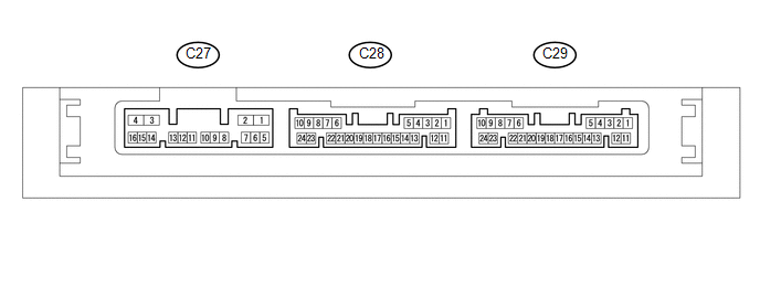
7. CHECK CERTIFICATION ECU (SMART KEY ECU ASSEMBLY) (w/ Smart Key System)
(a) Disconnect the C29 certification ECU (smart key ECU assembly) connector.
(b) Measure the voltage and resistance according to the value(s) in the table below.
HINT:
Measure the values on the wire harness side with the connector disconnected.
|
Tester Connection |
Wiring Color |
Terminal Description |
Condition |
Specified Condition |
|---|---|---|---|---|
|
C29-10 (+B) - C29-11 (E) |
P - W-B |
Battery power supply |
Always |
11 to 14 V |
|
C29-11 (E) - Body ground |
W-B - Body ground |
Ground |
Always |
Below 1 Ω |
If the result is not as specified, there may be a malfunction in the wire harness.
(c) Reconnect the C29 certification ECU (smart key ECU assembly) connector.
(d) Measure the voltage and check for pulses according to the value(s) in the table below.
|
Tester Connection |
Wiring Color |
Terminal Description |
Condition |
Specified Condition |
|---|---|---|---|---|
|
C29-6 (LIN) - C29-11 (E) |
L - W-B |
LIN communication line |
Ignition switch ON |
Pulse generation |
If the result is not as specified, the certification ECU (smart key ECU assembly) may be malfunctioning.
8. CHECK STEERING LOCK ECU (STEERING LOCK ACTUATOR OR UPPER BRACKET ASSEMBLY) (w/ Smart Key System)
(a) Disconnect the S45 steering lock ECU (steering lock actuator or upper bracket assembly) connector.

(b) Measure the resistance and voltage according to the value(s) in the table below.
|
Terminal No. (Symbol) |
Wiring Color |
Terminal Description |
Condition |
Specified Condition |
|---|---|---|---|---|
|
S45-1 (GND) - Body ground |
W-B - Body ground |
Ground |
Always |
Below 1 Ω |
|
S45-7 (B) - S45-1 (GND) |
R - W-B |
Battery power supply |
Always |
11 to 14 V |
If the result is not as specified, there may be a malfunction on the wire harness side.
(c) Reconnect the S45 steering lock ECU (steering lock actuator or upper bracket assembly) connector.
(d) Measure the voltage and check for pulses according to the value(s) in the table below.
|
Tester Connection |
Wiring Color |
Terminal Description |
Condition |
Specified Condition |
|---|---|---|---|---|
|
S45-5 (LIN) - S45-1 (GND) |
L - W-B |
LIN communication line |
Ignition switch ON |
Pulse generation |
If the result is not as specified, the steering lock ECU (steering lock actuator or upper bracket assembly) may be malfunctioning.
 How To Proceed With Troubleshooting
CAUTION / NOTICE / HINT
HINT:
Use the following procedure to troubleshoot the LIN communication system.
*: Use the Techstream.
PROCEDURE
1.
VEHICLE BROU ...
 Data List / Active Test
DATA LIST / ACTIVE TEST
1. DATA LIST
HINT:
Using the Techstream to read the Data List allows the values or states of switches,
sensors, actuators and other items to be read without removing any p ...
Other materials:
Inspection
INSPECTION
PROCEDURE
1. INSPECT INPUT SHAFT
(a) Using a dial indicator and 2 V-blocks, measure the shaft runout.
Maximum runout:
0.03 mm (0.0012 in.)
If the runout is more than the maximum, replace the input shaft.
HINT:
Measure the 3 areas shown in the illustration wit ...
How To Proceed With Troubleshooting
CAUTION / NOTICE / HINT
HINT:
Perform the following procedure to troubleshoot the dynamic radar cruise
control system.
*: Use the Techstream.
PROCEDURE
1.
VEHICLE BROUGHT TO WORKSHOP
NEXT
...
Cruise Control Main Switch
Components
COMPONENTS
ILLUSTRATION
Removal
REMOVAL
PROCEDURE
1. REMOVE STEERING PAD ASSEMBLY
(See page )
2. REMOVE CRUISE CONTROL MAIN SWITCH
(a) Disconnect the connector and remove the 2 screws.
(b) Remove the cruise ...
