Toyota Tacoma (2015-2018) Service Manual: Radio Antenna Cord
Components
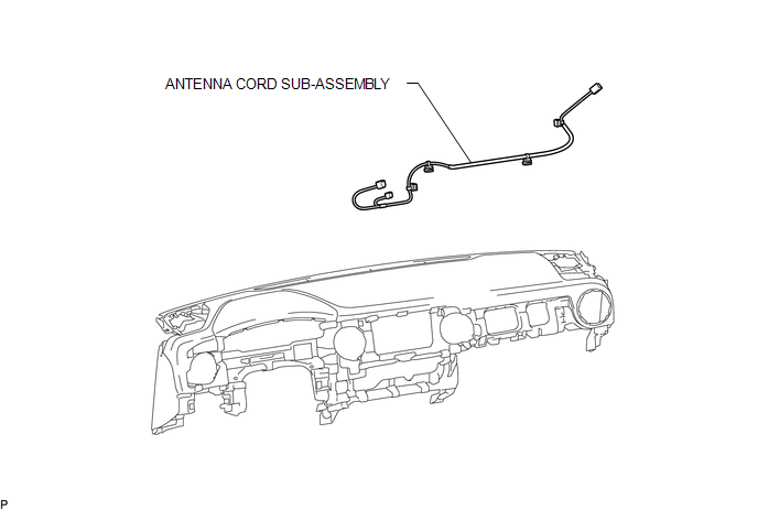
COMPONENTS
ILLUSTRATION
Removal
REMOVAL
PROCEDURE
1. REMOVE INSTRUMENT PANEL SUB-ASSEMBLY
(See page .gif) )
)
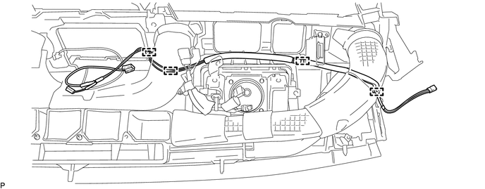
2. REMOVE ANTENNA CORD SUB-ASSEMBLY
(a) Disengage the 4 clamps to remove the antenna cord sub-assembly.
Installation
INSTALLATION
PROCEDURE
1. INSTALL ANTENNA CORD SUB-ASSEMBLY
(a) Engage the 4 clamps to install the antenna cord sub-assembly.
2. INSTALL INSTRUMENT PANEL SUB-ASSEMBLY
(See page .gif) )
)
 Radio Antenna
Components
COMPONENTS
ILLUSTRATION
Removal
REMOVAL
PROCEDURE
1. REMOVE ROOF HEADLINING ASSEMBLY (for Double Cab)
(See page )
2. REMOVE ROOF HEADLINING ASSEMBLY (for Access Cab)
(See p ...
 Radio Receiver
Components
COMPONENTS
ILLUSTRATION
ILLUSTRATION
Removal
REMOVAL
PROCEDURE
1. REMOVE INSTRUMENT CLUSTER CENTER FINISH PANEL SUB-ASSEMBLY
(See page )
2. REMOVE RADIO AND DISPLAY RECEI ...
Other materials:
System Diagram
SYSTEM DIAGRAM
Communication Table
Transmitting ECU (Transmitter)
Receiving ECU (Receiver)
Signal
Line
Main body ECU
(Multiplex Network Body ECU)
Combination Meter Assembly
Wireless door lock hazard warnin ...
Diagnostic Trouble Code Chart
DIAGNOSTIC TROUBLE CODE CHART
Main Body ECU (Multiplex Network Body ECU)
DTC Code
Detection Item
See page
B1206
P/W Master Switch Communication Stop
B1273
Sliding Roof ECU Communication Stop
...
TS and CG Terminal Circuit
DESCRIPTION
In Test Mode (signal check), a malfunction in the speed sensor that cannot be
detected when the vehicle is stopped can be detected while driving.
Sensor check mode can be entered by connecting terminals TS and CG of the DLC3
and turning the ignition switch from off to ON.
WIRING D ...
