Toyota Tacoma (2015-2018) Service Manual: Diagnosis System
DIAGNOSIS SYSTEM
DIAGNOSIS FUNCTION
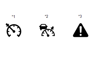
(a) The diagnosis function turns off the cruise control indicator, illuminates the master warning light and displays a warning message when a malfunction is detected. When a malfunction is detected in the dynamic radar cruise control system, DTCs are stored in the ECM or millimeter wave radar sensor assembly.
|
*1 |
Cruise Control Indicator (Constant Speed Control Mode) |
|
*2 |
Cruise Control Indicator (Vehicle-to-vehicle Distance Control Mode) |
|
*3 |
Master Warning Light |
NOTICE:
- If DTCs related to the communication system are stored, "Cruise Control Malfunction Visit Your Dealer", which is displayed in the combination meter assembly, disappears when the system returns to normal.
- If DTCs not related to the communication system are stored, "Cruise Control Malfunction Visit Your Dealer", which is displayed in the combination meter assembly, disappears when the ignition switch off then back ON after the system returns to normal.
DESCRIPTION
(a) The ECM and millimeter wave radar sensor assembly control the dynamic radar cruise control system of the vehicle. The data and DTCs relating to the dynamic radar cruise control system can be read from the DLC3 of the vehicle. Use the Techstream to check and solve the problem.
CHECK DLC3
(a) Check the DLC3.
Click here .gif)
CHECK INDICATOR
(a) Turn the ignition switch to ON.
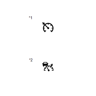
(b) Check that the cruise control indicator illuminates when the dynamic radar cruise control system is turned on using the cruise control main switch (ON-OFF button), and that the indicator turns off when the dynamic radar cruise control system is turned off using the cruise control main switch (ON-OFF button).
|
*1 |
Cruise Control Indicator (Constant Speed Control Mode) |
|
*2 |
Cruise Control Indicator (Vehicle-to-vehicle Distance Control Mode) |
 Road Test
ROAD TEST
PROBLEM SYMPTOM CONFIRMATION
HINT:
The dynamic radar cruise control system has 2 cruise control modes:
constant speed control mode and vehicle-to-vehicle distance control mode ...
 Problem Symptoms Table
PROBLEM SYMPTOMS TABLE
NOTICE:
Before replacing the ECM, refer to Registration.
w/o Smart Key System: Click here
w/ Smart Key System: Click here
When the millimeter wave rad ...
Other materials:
Removal
REMOVAL
PROCEDURE
1. REMOVE SLIDING ROOF SIDE GARNISH LH
(a) Fully open the sunshade trim sub-assembly.
(b) Remove the sliding roof side garnish LH.
2. REMOVE SLIDING ROOF SIDE GARNISH RH
HINT:
Use the same procedure as for the LH side.
3. ...
Components
COMPONENTS
ILLUSTRATION
*1
FRONT ARMREST BASE UPPER PANEL SUB-ASSEMBLY
*2
FRONT DOOR GLASS INNER WEATHERSTRIP
*3
FRONT DOOR INSIDE HANDLE BEZEL PLUG
*4
FRONT DOOR INSIDE HANDLE SUB-ASSEMBLY
...
Radio Receiver Power Source Circuit
DESCRIPTION
This is the power source circuit to operate the radio and display receiver assembly.
WIRING DIAGRAM
CAUTION / NOTICE / HINT
NOTICE:
Inspect the fuses for circuits related to this system before performing
the following inspection procedure.
PROCEDURE
...
