Toyota Tacoma (2015-2018) Service Manual: Radio Antenna
Components
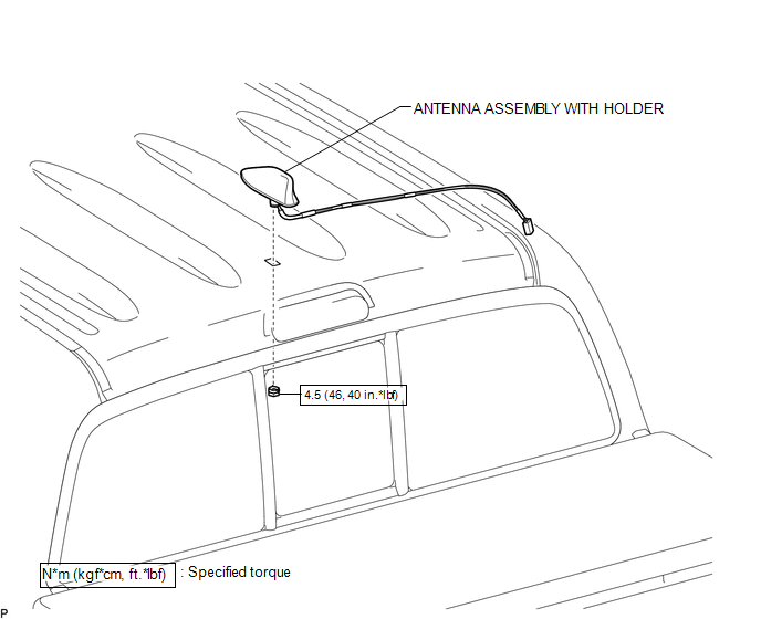
COMPONENTS
ILLUSTRATION
Removal
REMOVAL
PROCEDURE
1. REMOVE ROOF HEADLINING ASSEMBLY (for Double Cab)
(See page .gif) )
)
2. REMOVE ROOF HEADLINING ASSEMBLY (for Access Cab)
(See page )
3. REMOVE ANTENNA ASSEMBLY WITH HOLDER
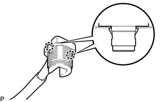
(a) Disengage the 3 clamps.
(b) Remove the nut.
|
(c) Disengage the 2 claws to remove the antenna assembly with holder. |
|
Installation
INSTALLATION
PROCEDURE
1. INSTALL ANTENNA ASSEMBLY WITH HOLDER
(a) Engage the 2 claws to install the antenna assembly with holder.
(b) Install the nut.
Torque:
4.5 N·m {46 kgf·cm, 40 in·lbf}
(c) Engage the 3 clamps.
2. INSTALL ROOF HEADLINING ASSEMBLY (for Double Cab)
(See page .gif) )
)
3. INSTALL ROOF HEADLINING ASSEMBLY (for Access Cab)
(See page )
 Noise Filter(for 2tr-fe)
Components
COMPONENTS
ILLUSTRATION
Removal
REMOVAL
PROCEDURE
1. DISCONNECT CABLE FROM NEGATIVE BATTERY TERMINAL
2. REMOVE AIR CLEANER ASSEMBLY
(See page )
3. REMOVE RADIO SETTING COND ...
 Radio Antenna Cord
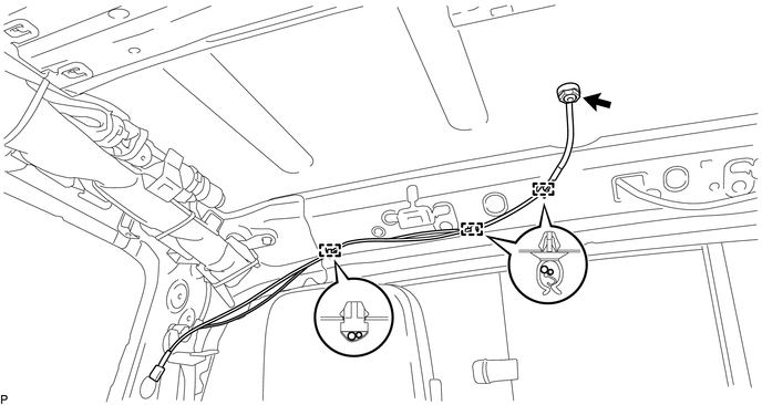
Components
COMPONENTS
ILLUSTRATION
Removal
REMOVAL
PROCEDURE
1. REMOVE INSTRUMENT PANEL SUB-ASSEMBLY
(See page )
2. REMOVE ANTENNA CORD SUB-ASSEMBLY
(a) Disengage the 4 clamps to remo ...
Other materials:
Diameter of the Tire is not Uniform (C1337)
DESCRIPTION
The skid control ECU (brake actuator assembly) measures the speed of each wheel
by receiving signals from the speed sensors. These signals are used for recognizing
whether all 4 wheels are operating properly. Therefore, all wheel signals must indicate
the same speed.
D ...
Front Upper Suspension Arm
Components
COMPONENTS
ILLUSTRATION
Disassembly
DISASSEMBLY
PROCEDURE
1. REMOVE FRONT SUSPENSION UPPER ARM BUSH
(a) Using a hammer and chisel, raise the flange of the bushing diagonally as
shown in the illustration.
(b) Using SST and a press, remove the front suspension u ...
Adjustment
ADJUSTMENT
PROCEDURE
1. ADJUST PARK/NEUTRAL POSITION SWITCH
(a) While pushing the shift lock release button, move the shift lever to N.
(b) Remove the bolt of the park/neutral position switch.
(c) Clean the bolt and bolt hole.
(d) Apply adhesive to 2 or 3 threads on the end of the bolt.
Adhes ...
